
Feeding mechanism, cutter cutting assembly and wood shaving machining device

A feeding mechanism and cutting tool technology, which is applied in the field of shaving processing, can solve the problems of low processing efficiency and achieve the effects of prolonging service life, high space utilization and reasonable structure

Active Publication Date: 2021-09-03
TREEZO NEW MATERIAL TECH GRP CO LTD
View PDF15 Cites 2 Cited by
  • Summary
  • Abstract
  • Description
  • Claims
  • Application Information

AI Technical Summary

Problems solved by technology

[0003] The invention provides a feeding mechanism, a tool cutting assembly and a shaving processing device, which overcomes the above-mentioned deficiencies in the prior art, and can effectively solve the problem of low processing efficiency in the existing bamboo shaving processing device

Method used


Image

  • Feeding mechanism, cutter cutting assembly and wood shaving machining device
  • Feeding mechanism, cutter cutting assembly and wood shaving machining device
  • Feeding mechanism, cutter cutting assembly and wood shaving machining device

Examples


Embodiment 1

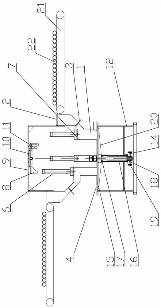
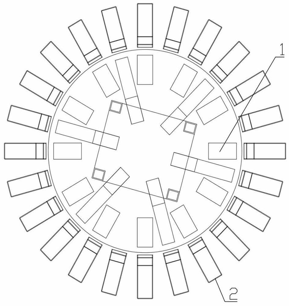
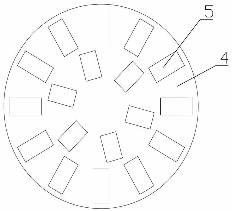
[0039] Embodiment one: as attached Figure 1-3As shown, the feeding mechanism includes a pressing bin 1, a rotating feeding bin 2 and a material baffle 3, and establishes a horizontal reference plane and a reference axis perpendicular to the horizontal reference plane, which are distributed from inside to outside on the outside of the reference axis. There are at least two reference rings, and each reference ring includes at least two reference points spaced around the reference axis along the circumference, and the horizontal reference plane, reference axis, reference ring and reference point are all virtual; corresponding to each Each reference point position is provided with a press bin 1 whose outlet is located at the reference point, the end faces of the outlets of all press bins 1 are located on the horizontal reference plane, and the top of the press bin 1 is provided with a feed port, each A rotary feeding bin 2 is provided at the feeding port, and all the rotating fee...

Embodiment 2

[0051] Embodiment 2: The difference between this embodiment and Embodiment 1 is: as attached Figure 4 As shown, the reference ring has three inner, middle and outer rings. The inner reference ring includes 4 reference points evenly spaced along the circumferential direction, and the middle reference ring includes 8 reference points evenly spaced along the circumferential direction. The reference ring of the outer ring includes 16 reference points evenly distributed along the circumferential direction, that is, the processing opening 5 is also three circles in the inner, middle and outer circles, and the inner ring includes 4 processing openings 5 ​​evenly distributed along the circumferential direction. The ring includes 8 processing openings 5 ​​evenly distributed along the circumferential direction, and the outer ring includes 16 processing openings 5 ​​evenly distributed along the circumferential direction, thereby further increasing the material area that can be planed whe...

Embodiment 3

[0052] Embodiment 3: The difference between this embodiment and Embodiment 1 is that each processing port 5 is provided with a processing port baffle that can be opened and closed. The processing port baffle can cover the processing port 5, and a driving structure capable of reciprocating motion can be selected. For example, a cylinder drive can be selected. The driving of the processing port baffle is controlled according to the position signal of the piston rod of the corresponding pressing cylinder 6. When the position signal When it is in the original position, the processing port baffle covers the processing port 5 to prevent the material from bouncing up due to the contact between the material and the tool. When the position signal is at the original position again, the processing port baffle moves laterally again until covering the processing port 5 .


PUM


Abstract

The invention relates to the technical field of wood shaving machining, in particular to a feeding mechanism, a cutter cutting assembly and a wood shaving machining device. The feeding mechanism comprises material pressing bins, rotary feeding bins and a material baffle, and at least two circles of reference annular belts are distributed on the outer side of a reference axis at intervals from inside to outside. One material pressing bin with an outlet located at the reference point position is arranged at the position corresponding to each reference point position, the end faces of the outlets of all the material pressing bins are located on the horizontal reference plane, a feeding inlet is formed in the upper portion of each material pressing bin, one rotary feeding bin is arranged at each feeding inlet, and all the rotary feeding bins can rotate around the reference axis. The lower portion of each rotary feeding bin is provided with a conveying opening capable of being in butt joint with the corresponding feeding inlet. The feeding mechanism is reasonable and compact in structure and convenient to use, through the arrangement of the material pressing bins and the rotary feeding bins, feeding can be conducted on at least two layers of annularly-formed machining openings, so that the material slicing area of a cutter is increased, the machining efficiency is improved, and the characteristics of use safety, efficiency and convenience are achieved.

Description

technical field [0001] The invention relates to the technical field of shaving processing, and relates to a feeding mechanism, a tool cutting assembly and a shaving processing device. Background technique [0002] Wood shaving machine is mainly used to produce flake shavings. For example, the application number is CN201920999436.4, and the name is a Chinese utility model patent for a production device of long shavings for OSB particle board processing. Another example is the application number CN201920773358.6, and the name is a kind of Another example is the Chinese utility model patent for board processing equipment, and the application number is CN201810815968.8, and the Chinese invention patent named wood planer. However, the cutting and feeding methods of the existing shaving machines are inefficient and affect the production progress. Contents of the invention [0003] The invention provides a feeding mechanism, a tool cutting assembly and a shaving processing devic...

Claims


Application Information

Patent Timeline
Patent Type & Authority Applications(China)
IPC IPC(8): B27L11/02
CPCB27L11/02
Inventor 陆铜华郝玉东毕海明
Owner TREEZO NEW MATERIAL TECH GRP CO LTD
Learn More