
Great earthquake impending earthquake sound monitoring probe unit structure based on piezoelectric cable sensor and circuit module structure

A piezoelectric cable and monitoring probe technology, applied in the direction of seismic signal receivers, etc., can solve the problems that the direction of the sound source of the geoacoustic signal cannot be accurately determined, the geoacoustic signal cannot be detected effectively, and the sensors are not densely installed. The effect of low cost, high reliability and high sensitivity

Inactive Publication Date: 2016-07-13
PEKING UNIV SHENZHEN GRADUATE SCHOOL
View PDF12 Cites 3 Cited by
  • Summary
  • Abstract
  • Description
  • Claims
  • Application Information

AI Technical Summary

Problems solved by technology

First of all, since the use of hydrophones to detect geoacoustic information in earthquakes requires that the sensor probes must be installed in deep water wells, the geographical range of its application is narrow and the application conditions are harsh; secondly, the acoustic waves that piezoelectric ceramic sensors or acoustic emission sensors can cover The spectrum range is small, and the acoustic spectrum of the geoacoustic signal spans infrasonic waves, audible waves, and ultrasonic waves, so that the use of a single type of piezoelectric ceramic sensor or acoustic emission sensor cannot effectively detect all geoacoustic signals; None of them are densely installed on the detection probe or detection surface, so that the sound source direction of the geoacoustic signal cannot be accurately determined

Method used


Image

  • Great earthquake impending earthquake sound monitoring probe unit structure based on piezoelectric cable sensor and circuit module structure
  • Great earthquake impending earthquake sound monitoring probe unit structure based on piezoelectric cable sensor and circuit module structure
  • Great earthquake impending earthquake sound monitoring probe unit structure based on piezoelectric cable sensor and circuit module structure

Examples


Embodiment Construction

[0038] specific implementation plan

[0039] In order to make the purpose, technical solutions and advantages of the present invention more clear, the best implementation for implementing the present invention will be described below with reference to the accompanying drawings.

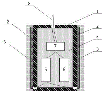
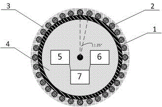
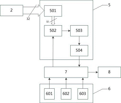
[0040] Such as figure 1 and figure 2 As shown, the probe unit structure of the imminent earthquake geoacoustic monitoring probe based on the piezoelectric cable sensor includes: a cylindrical cavity 1, a beam-shaped piezoelectric cable sensor array 2, an encapsulating body 3, a filling body 4, and a front-end preprocessing circuit Module 5, calibration circuit module 6, control and signal processing module 7, power supply and signal transmission cable 8.

[0041] Such as figure 2 As shown, each piezoelectric cable in the bundle-type piezoelectric cable sensor array 2 is attached to the outside of the cylindrical cavity 1 in a circular, equidistant, and dense arrangement; the encapsulant 3 evenly...


PUM


Abstract

The present invention discloses a great earthquake impending earthquake sound monitoring probe unit structure based on a piezoelectric cable sensor and a circuit module structure. According to the probe unit structure, a beam type piezoelectric cable sensor array is employed, each piezoelectric cable is attached to the outer side of a probe unit cylindrical cavity in a mode of annular, isometric and dense arrangement and is uniformly covered by a package colloid, through analyzing the intensity of the earthquake sound signal received by each cable, an earthquake sound source direction can be judged precisely. In addition, a time control multi-way switch is employed by a probe circuit module structure carries out time-sharing processing of each piezoelectric cable, and a processing circuit topology structure is simplified. Finally, a calibration circuit module is used to calibrate and measure the azimuth error before and after probe installation to provide the basis of orientation compensation for signal processing, and the precise record of the source direction of the earthquake sound source wave signal is ensured. Through the above technical scheme, the probe can be densely laid in a large scale in a bed rock or compact soil of 100m to 150m underground in an earthquake fault zone, and thus the great earthquake impending earthquake sound monitoring can be reliably developed with low cost for a long time.

Description

technical field [0001] The patent of the invention relates to the field of sensor structure and circuit design for imminent earthquake monitoring, and specifically relates to a low-cost, high-reliability imminent earthquake monitoring probe based on a piezoelectric cable sensor that can accurately determine the direction of the source of ground sound. The unit structure and its circuit module structure. Background technique [0002] After continuous movement and changes, the earth has gradually accumulated huge energy, causing sudden rupture of rocks in some fragile areas of the earth's crust, or triggering the dislocation of original faults. This is an earthquake. Strengthening research on countermeasures against earthquake disasters, improving the technical level of earthquake monitoring and prediction, and mitigating earthquake disasters are directly related and of great significance to the development of the country, the stability of society and the safety of people's li...

Claims


Application Information

Patent Timeline
Patent Type & Authority Applications(China)
IPC IPC(8): G01V1/18
Inventor 王新安林科雍珊珊韩朝相曾敬武
Owner PEKING UNIV SHENZHEN GRADUATE SCHOOL
Learn More