Signal lamp control system

A technology for signal light control and signal emission, which is used in the control of traffic signals and other directions to achieve the effect of reducing workload, shortening residence time, and optimizing urban environment.

Inactive Publication Date: 2016-07-13
江苏智融高科信息科技有限公司
View PDF3 Cites 2 Cited by
  • Summary
  • Abstract
  • Description
  • Claims
  • Application Information

AI Technical Summary

Problems solved by technology

[0003] The purpose of the present invention is to solve the problem of the existing traffic control system simply by controlling traffic lights

Method used


Image

  • Signal lamp control system
  • Signal lamp control system

Examples


Embodiment Construction

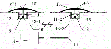
[0016] Illustrate the specific embodiment of the present invention in conjunction with accompanying drawing: signal light control system, comprises vehicle-mounted part,

[0017] The road surface part, the control center 14 and several information transmission devices 16, the vehicle part includes a receiving signal unit, the road surface part includes a sensing unit and a transmitting signal unit, the signal receiving unit is installed on the car, and the sensing unit is located in the first road surface groove In 8-1, the transmitting signal unit is located in the second road surface groove 8-2;

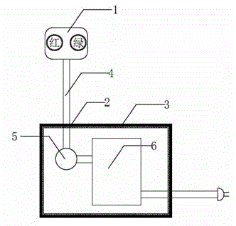
[0018] The signal receiving unit includes a housing 3, a signal lamp 1, a wireless receiver 6, a time controller 5 and several wires 4, the time controller 5 and the wireless receiver 6 are placed in the housing, and the wireless receiver 6 passes through the wire 4 Establish a connection with the vehicle-mounted traffic light 1, the time controller 5 is placed between the signal l...


PUM


Abstract

The invention relates to a signal lamp control system. The aim of the invention lies in solving problems that a conventional traffic control system just depends on traffic signal lights for traffic dispersion, is not good in guiding effect during rush hours, and is not flexile in dispersion mode. The system comprises a signal receiving unit, and the signal receiving unit comprises a housing, a vehicle-mounted signal lamp, a wireless receiver, a time controller, and a plurality of wires. The time controller and the wireless receiver are disposed in the housing, and the wireless receiver is connected with the vehicle-mounted signal lamp through a wire. The time controller is disposed between the vehicle-mounted signal lamp and the wireless receiver. A vehicle body power supply is used for supplying power to the signal receiving unit. The system can receive the congestion information of each road, and displays the congestion information through signal lights. The system can iron out the defect that a conventional road just depends on the traffic signal lights, effectively shortens the waiting time of a passing vehicle, and alleviates the urban traffic pressure.

Description

technical field [0001] The invention relates to a signal lamp control system, in particular to a mobile signal lamp control system. Background technique [0002] As everyone knows, the road traffic lights used in society today mostly adopt fixed time control methods. To a certain extent, there is great irrationality. The amount of traffic on the lane can only be passed within the specified time, and it is also necessary to follow the same long waiting time under the situation of a small number of cars, which seriously prolongs the retention time of the car on the road. For this problem, many scholars have also done a lot of research, such as obtaining the traffic flow level through the camera imaging system to control the traffic light time, and the traffic light control system based on the single-chip microcomputer. Contents of the invention [0003] The purpose of the present invention is to solve the problem of the existing traffic control system simply by controlling...

Claims


Application Information

Patent Timeline
IPC IPC(8): G08G1/07
Inventor 徐晓声
Owner 江苏智融高科信息科技有限公司
Why Eureka
Try Eureka