

Heating equipment of oil filtering machine
A technology of heating equipment and oil filter, applied in the direction of filtration separation, filtration circuit, separation method, etc., can solve the problems of high energy consumption, large noise pollution, high maintenance cost, etc., and achieve the goal of increasing heating time, increasing efficiency, and extending time Effect
Inactive Publication Date: 2016-07-20
HARBIN HONGWANZHI SCI & TECH DEV
View PDF0 Cites 0 Cited by
- Summary
- Abstract
- Description
- Claims
- Application Information
AI Technical Summary
Problems solved by technology
[0006] At present, most of the oil filter heating equipment on the market has the disadvantages of high energy consumption, high noise pollution, and high maintenance costs.
Method used
View moreImage
Smart ImageViewing Examples

Examples
Embodiment 1
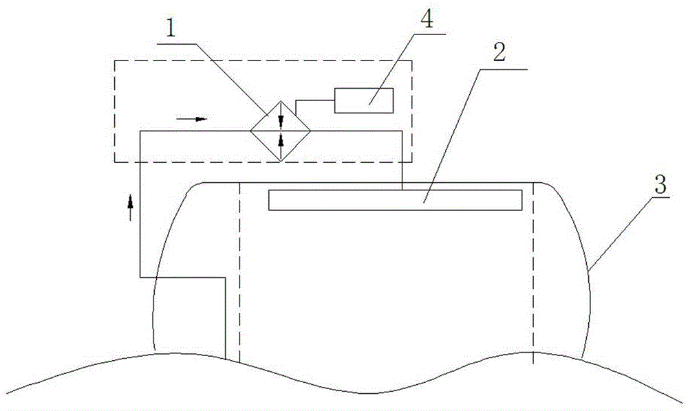
[0014] A heating device for an oil filter, including a heater 1, a particle separator 2, etc., characterized in that the particle separator 1 is arranged inside the vacuum separation device 3 of the oil filter, and the particle separator 1 is externally connected to the heater 2, The other end of heater 2 is connected with oil supply equipment.
Embodiment 2
[0016] The heater 2 is provided with a fuzzy temperature controller 4 .
Login to View More PUM
 Abstract
The invention discloses heating equipment of oil filtering machine. The heating equipment comprises a heater and a particle type separator. The particle type separator is arranged in vacuum separating equipment of oil filtering machine and is externally connected to the heater; the other end of the heater is connected to an oil supply facility, and the heater is provided with a fuzzy temperature control instrument. By using a fuzzy temperature control technology, the heating time and technology for purifying oil are improved, the oil temperature can be controlled under 70 DEG C, the oil quality can be maintained, the structure of oil molecules is not destroyed, the heated oil can be effectively discharged by the particle type heater, the oil is stirred in the vacuum space of the vacuum separating equipment so as to separate impurities (water and gas) from oil, and the disqualified transformer oil is processed so as to obtain an oil product that can meet the national and international standards.
Description
technical field [0001] The invention relates to an oil filter technology, in particular to a heating device for an oil filter. Background technique [0002] Oil filter, also known as oil filter, oil purifier. Its function is to filter and purify the contaminated oil, restore or improve the properties of the oil itself, including the cleanliness of the oil, water content, gas content, acid value, viscosity, flash point, dielectric strength, color, etc. , In addition, it can effectively remove impurities in oil products to ensure the safe operation of oil-using equipment. [0003] When the oil filter is working, the oil enters the primary filter through the inlet under the action of the internal and external pressure difference, and the large particles of impurities are filtered out. In the device, a mist is first formed, and then a film is formed, so that the contact area in the vacuum is expanded to hundreds of times of the original, and the water in the oil is quickly abs...
Claims
Login to View More Application Information
Patent Timeline
 Patent Type & AuthorityApplications(China)
IPC IPC(8): B01D35/18B01D36/00
Inventor王雷
OwnerHARBIN HONGWANZHI SCI & TECH DEV