Online testing method for ultra-view-field cutter

A detection method and cutting tool technology, applied in the direction of manufacturing tools, measuring/indicating equipment, metal processing equipment, etc., can solve the problems of reduced processing accuracy and processing efficiency, secondary clamping error, and reduced detection efficiency, so as to improve processing accuracy and efficiency, avoiding secondary clamping errors, and improving service life

Active Publication Date: 2016-07-20
TIANJIN UNIV
View PDF8 Cites 23 Cited by
  • Summary
  • Abstract
  • Description
  • Claims
  • Application Information

AI Technical Summary

Problems solved by technology

[0007] Most of the measurement methods and products are limited by the measurement principle, and can only be made into independent devices, which cannot realize online / on-machine detection, and can only be measured offline in stages during the processing process, so the tool cannot obtain the shape information of the cutting edge in time, resulting in It is impossible to monitor the wear of the tool in time; at the same time, multiple off-line measurements may cause secondary clamping errors, resulting in reduced machining accuracy and efficiency;
[0008] The existing image-based direct tool measurement methods and products, in order to ensure the precise measurement of small-sized tools, use optical lenses with large magnification and small field of view. When measuring large-sized tools, the image exceeds the field of view and cannot accurately obtain the tool cutting. The shape information of the blade can only be replaced by a small magnification large field of view lens, which will lead to a decrease in measurement accuracy, and increase the preparation time for equipment installation and adjustment, and reduce detection efficiency.

Method used


Image

  • Online testing method for ultra-view-field cutter
  • Online testing method for ultra-view-field cutter
  • Online testing method for ultra-view-field cutter

Examples


Embodiment 1

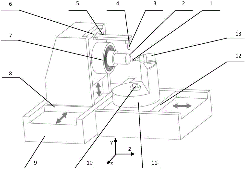
[0058] (1) Open the telecentric parallel light source 10 installed on the machine tool rotary workbench, initialize the CCD camera 4 connected to the computer by the image acquisition card, display the CCD camera image on the display of the computer, and the CCD camera is installed on On the translation table of the machine tool;

[0059] (2) Use the machine tool control system to drive the translation table of the machine tool to drive the CCD camera to move to the top of the tool to be detected installed on the rotary table 11, and control the translation work table to drive the CCD camera to move to achieve the focus on the tool to be detected, The focused image is displayed on the monitor of the computer, and the cutting edge of the tool to be detected is in the center of the telecentric parallel light source;

[0060] (3) According to the focused image of the CCD camera and the tool displayed on the monitor, the tool is moved by moving the table so that the cutting edge o...


PUM


Abstract

The invention discloses an online testing method for an ultra-view-field cutter. The online testing method includes the steps that a machine-tool control system is used for driving a transverse movement working table of a machine tool to drive a CCD camera to move to the position above the cutter which needs to be detected and is installed on a rotary working table, and controlling the transverse movement working table to drive the CCD camera to move so as to achieve focusing of the cutter needing to be detected; the transverse movement working table drives the cutter to move to enable a cutter cutting blade to be located in the center of a view field of the CCD camera, the center of the cutting blade and the center of a rotary table are coincided, and the position is set to be the initial position of the cutter; indexing rotation is carried out with the initial position as the symmetric point; coordinates of all sample points of a sub pixel peripheral point group at the edge of the cutting blade and direction vectors of all sample points are obtained; and every two adjacent images are matched and jointed. By means of the method, the machining accuracy and efficiency of complicated surfaces are greatly improved.

Description

technical field [0001] The invention relates to the technical field of precision and ultra-precision machining of complex-shaped surface components, in particular to an image processing technology-based online detection (monitoring) of the shape parameters and wear conditions of the tool's working edge, which can realize the shape and wear of the tool's working edge at any time. Accurate online detection (monitoring), and then realize the efficient and high-precision processing method for complex surface components. Background technique [0002] With the continuous development and progress of science and technology, equipment and systems in various fields are constantly developing towards ultra-precision and miniaturization. Complex surface components such as aspheric surfaces, free-form surfaces, and arrays have gained more and more applications due to their superior functionality. The core components of digital appliances that are closely related to people's lives, such a...

Claims


Application Information

Patent Timeline
Patent Type & Authority Applications(China)
IPC IPC(8): B23Q17/09B23Q17/24
CPCB23Q17/2409B23Q17/2457
Inventor 仇中军马壮徐露艳
Owner TIANJIN UNIV
Why Eureka
Try Eureka