
Glue laminating process

A technology of colloid and process, which is applied in the field of colloid lamination technology, can solve the problems of bad fog, affecting IR holes, and low yield of colloid lamination, so as to solve the problem of lamination air bubbles, improve lamination accuracy, and shorten production time Effect

Inactive Publication Date: 2016-07-20
TRULY OPTO ELECTRONICS
View PDF2 Cites 10 Cited by
  • Summary
  • Abstract
  • Description
  • Claims
  • Application Information

AI Technical Summary

Problems solved by technology

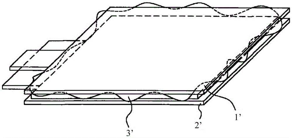
However, when the pressure is applied to the substrate 1', since the glue 3' will flow, it is easy to cause glue overflow around the substrate 1' and the display panel 2', and the amount of glue overflow cannot be precisely controlled. Affect the IR hole, resulting in product scrap
At the same time, foggy defects are prone to occur in the laminated box, and it is unavoidable to repair the defect in the box, which leads to scrapping. If there is a defect in the box, it cannot be repaired, and the quality cannot be guaranteed after repair, resulting in a low colloidal pressing yield.
[0003] In the prior art, there is a cofferdam-type pressing method by dispensing and pre-curing around the substrate or pre-curing around the colloid after dispensing to solve the problem of glue overflow. Although the problem of glue overflow can be solved, there are the following problems: Insufficient points: 1) The glue overflow cannot be precisely controlled, and the glue still has a certain fluidity after pre-curing, which will cause precision problems and the operation is difficult; 2) Pre-curing around the glue after dispensing on the substrate requires the glue to flow naturally It can only play a role after being leveled. The actual operation is difficult and not easy to achieve, and natural leveling takes time, which reduces the actual production efficiency; The edge has been pre-cured, and then the alignment is pressed. At this time, there will be pressing air bubbles. The air bubbles can only use the vent hole. If there is a vent hole, there will be glue overflow, which still cannot actually solve the glue overflow problem.

Method used


Image

  • Glue laminating process
  • Glue laminating process
  • Glue laminating process

Examples


Embodiment Construction

[0023] The present invention will be described in detail below in conjunction with the accompanying drawings and embodiments.

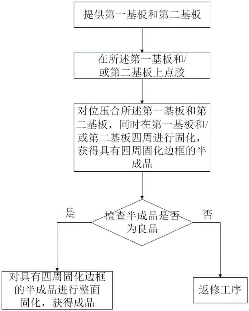
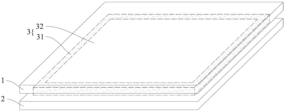
[0024] Please refer to Figures 2 to 4 , the colloid bonding process of a preferred embodiment of the present invention comprises the following steps:

[0025] (1) providing a first substrate 1 and a second substrate 2;

[0026] In specific implementation, the first substrate 1 and the second substrate 2 shown can be a touch screen (TouchPanel, TP), a liquid crystal display module (LiquidCrystalModule, LCM), a glass cover (CoverGlass, CG) or a sensor glass (SensorGlass, SG ), but not limited to this.

[0027] (2) Dispensing glue on the first substrate 1 and / or the second substrate 2;

[0028] During specific implementation, the colloid used may be ultraviolet glue, heat-curing glue, or a combination of the two. The glue coating can be applied on the substrate by screen printing or dot-by-dot printing, but not limited to these two methods.

[0029...


PUM

PropertyMeasurementUnit
widthaaaaaaaaaa

Abstract

The invention provides a glue laminating process. The glue laminating process comprises the following steps: (1) providing a first substrate and a second substrate; (2) dispensing a glue to the first substrate and / or the second substrate; (3) carrying out aligned press-fitting on the first substrate and the second substrate, and meanwhile, curing the periphery of the first substrate and / or the second substrate so as to obtain a semifinished product with a periphery-cured frame; and (4) carrying out surface-dressing curing on the semifinished product with the periphery-cured frame, thereby obtaining a finished product. According to the glue laminating process, the periphery of the substrates is cured while the aligned press-fitting of the substrates is completed so as to obtain the periphery-cured frame, thus, the problem of glue overflowing is effectively solved, the width of overflowed glue can be accurately controlled, the broadening of the glue does not occur after curing, secondary misalignment does not occur after curing, the accuracy of press-fitting is further improved, and the actual operation of a production line is facilitated; and the problem of press-fit bubbles can be effectively solved, the leveling of the glue is accelerated, the production time is shortened, and the production efficiency is further increased.

Description

technical field [0001] The invention relates to a colloid bonding process. Background technique [0002] figure 1 It is a schematic diagram of glue overflow during substrate lamination process in the prior art. Please refer to figure 1 In the prior art, when the substrate 1' is to be bonded to the display panel 2', the glue 3' is usually first coated on the display panel 2', and then the substrate 1' is stacked on the display panel 2'. Afterwards, pressure is applied to the substrate 1' to press the substrate 1' and the display panel 2'. Then, a colloid curing process is performed to solidify the colloid 3', so that the substrate 1' and the display panel 2' can be bonded by the colloid 3'. However, when pressure is applied to the substrate 1', since the glue 3' will flow, it is easy to cause glue overflow around the substrate 1' and the display panel 2', and the amount of glue overflow cannot be precisely controlled. Affect the IR hole, resulting in product scrapping. ...

Claims


Application Information

Patent Timeline
Patent Type & Authority Applications(China)
IPC IPC(8): B32B37/12B32B38/18B32B37/10B32B38/00
CPCB32B37/10B32B37/1284B32B38/00B32B38/1841B32B2038/0076
Inventor 黄梨存曾一鑫丁俊许传健卓志健龙安川
Owner TRULY OPTO ELECTRONICS
Learn More