
A sinking and floating river hydroelectric power station

A power station and hydropower technology, applied in hydropower, engine components, machines/engines, etc., can solve the problems of damaged river flood discharge capacity, waste of power generation capacity, low income, etc., to achieve energy saving and environmental protection, ensure flood discharge capacity, The effect of low construction cost

Active Publication Date: 2018-01-02
旺苍县科美防震科技有限公司
View PDF6 Cites 1 Cited by
  • Summary
  • Abstract
  • Description
  • Claims
  • Application Information

AI Technical Summary

Problems solved by technology

[0003] However, in reality, the river course is usually not suitable for the construction of hydropower stations, and there is a huge waste of water energy in the river course
Due to the large changes in the water volume of the river in different periods, if large and medium-sized hydropower stations are built on the river, the power generation efficiency of the hydropower station will be low during the dry season, and there will be a huge waste of power generation capacity. Compared with the construction cost, the benefits will be very low
If a small hydropower station is built on the river, the flood discharge capacity of the river will be damaged during the wet season, which will easily lead to floods and damage the farmland and houses on both sides of the river.

Method used


Image

  • A sinking and floating river hydroelectric power station

Examples


Embodiment 1

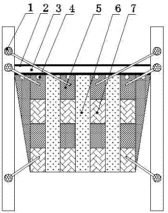
[0026] see figure 1 , a sinking-floating river hydropower station, comprising a ridge 2 connecting the two banks of the river and a sinking-floating hydropower generating device, the ridge 2 is provided with a groove 3, and a column pile is arranged behind the groove 3, The sinking-floating hydropower generating device is located on the groove 3, and the contact surface between the sinking-floating hydropower generating device and the embankment 2 is a dam and a sluice, and the sinking-floating hydropower generating device includes a buoyancy chamber 5, a sluice, and a water turbine. and a generator 7, the sinking-floating hydroelectric power generation device is provided with a pile hole 4 and a flow tank 6, the pile hole 4 is pierced with a pile, and the flow groove 6 is provided with a water turbine.

[0027] In the present invention, the sinking-floating river channel hydropower station is built in the section where the fast water flow impacts. The embankment 2 intercepts...


PUM


Abstract

The invention discloses an up-and-down river channel water energy power station. The up-and-down river channel water energy power station comprises a dam connecting two banks of a river channel, and an up-and-down water energy power generating device. A groove is formed in the dam. Column piles are arranged behind the groove. The up-and-down water energy power generating device is located on the groove, and the face, in contact with the dam, of the up-and-down water energy power generating device is provided with a barrage and a sluice. The up-and-down water energy power generating device comprises buoyancy bins, sluices, a water turbine and power generators. The up-and-down water energy power generating device is provided with column pile holes and a water flowing groove. The column piles penetrate into the column pile holes. The water turbine is arranged in the water flowing groove. The defect that a power station is not suitable for being built on a river channel is overcome; compared with large-sized and medium-sized power stations, the up-and-down river channel water energy power station is low in construction cost and high in power generation efficiency; compared with small power stations, the up-and-down river channel water energy power station can sufficiently utilize the water energy of the river channel and can also ensure the flood discharge capability of the river channel, floods are avoided, the flood discharge capability of the river channel is prevented from being damaged in the high-water period, and farmland and houses on the two banks are protected against floods.

Description

technical field [0001] The invention relates to the field of hydropower generation, in particular to a sinking-floating river hydropower station. Background technique [0002] A river course refers to the route through which river water flows, and usually refers to a navigable waterway. According to the abundance of water, there are dry seasons and wet seasons in the river. In theory, rivers are rich in water energy. If power stations can be built in tidal flats of rivers and areas impacted by fast water flow, it will not only achieve energy conservation and environmental protection, but also benefit the vigorous development of my country's economic construction. [0003] However, in practice, river courses are usually not suitable for building hydropower stations, and there is a huge waste of water energy in the river courses. Since the amount of water in the river varies greatly in different periods, if a large or medium-sized hydropower station is built on the river, th...

Claims


Application Information

Patent Timeline
Patent Type & Authority Patents(China)
IPC IPC(8): F03B13/08
CPCF03B13/08Y02E10/20
Inventor 汤正云
Owner 旺苍县科美防震科技有限公司
Learn More