Cooling and heating integrated carbon dioxide heat pump device

A carbon dioxide and heat pump device technology, applied in refrigeration and liquefaction, refrigerators, refrigeration components, etc., can solve the problems of energy efficiency and heating capacity decay, energy efficiency advantages no longer exist, and cannot meet user needs, etc., to achieve large refrigeration capacity, Solve the pollution problem and reduce the effect of the global warming effect

Active Publication Date: 2016-07-20
NANJING CANATAL DATA CENT ENVIRONMENTAL TECH CO LTD
View PDF2 Cites 7 Cited by
  • Summary
  • Abstract
  • Description
  • Claims
  • Application Information

AI Technical Summary

Problems solved by technology

Most heat pump devices adopt the circulation heating method and are equipped with an auxiliary electric heating system. When the ambient temperature is lower than 0°C, the auxiliary electric heating is started to meet the needs of users, but the energy efficiency advantage no longer exists. Moreover, when the ambient temperature is lower than -7 ℃, the heat pump system is forbidden to use, just like a single electric water heater, which basically cannot meet the needs of users
[0003] There are also those who use frequency conversion system or digital scroll system, which only make the ambient temperature of the product lower. However, when the ambient temperature is below -12°C, the energy efficiency and heating capacity will be greatly reduced, and it cannot be used normally.
[0004] Some specially designed heat pump devices can produce hot water not exceeding 60°C in summer. When the ambient temperature is lower, the heating capacity of conventional heat pump devices is smaller, the heating time is prolonged, and the energy efficiency ratio will be lower.
It absorbs very little heat from the air, and it is no longer possible to rely on heat pumps to produce hot water
Therefore, conventional heat pump devices are suitable for use in areas south of the Yangtze River, but cannot be used in winter in cold areas, and the use environment is greatly restricted

Method used


Image

  • Cooling and heating integrated carbon dioxide heat pump device
  • Cooling and heating integrated carbon dioxide heat pump device
  • Cooling and heating integrated carbon dioxide heat pump device

Examples


Embodiment Construction

[0029] Below in conjunction with specific embodiment, further illustrate the present invention, should be understood that these embodiments are only used to illustrate the present invention and are not intended to limit the scope of the present invention, after having read the present invention, those skilled in the art will understand various equivalent forms of the present invention All modifications fall within the scope defined by the appended claims of the present application.

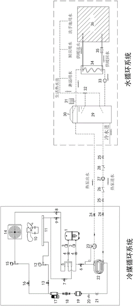
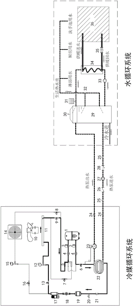
[0030] Such as figure 1 As shown, a cooling and heating integrated carbon dioxide heat pump device disclosed in the embodiment of the present invention includes two parts: a refrigerant circulation system and a hot water circulation system, wherein the refrigerant circulation system is mainly composed of a carbon dioxide DC inverter compressor 1, a water-refrigerant heat exchanger 22. Solenoid valve 17, electronic expansion valve 12 / 15, outdoor heat exchanger 11, outdoor fan 10, indoor unit 14, fo...


PUM


Abstract

The invention discloses a cooling and heating integrated carbon dioxide heat pump device. The cooling and heating integrated carbon dioxide heat pump device comprises a refrigerant circulation system and a hot water circulation system, wherein the refrigerant circulation system mainly comprises a carbon dioxide compressor, a four-way reversing valve, an outdoor fan, an outdoor heat exchanger, an electronic expansion valve, an indoor unit, a solenoid valve, a water-refrigerant heat exchanger and the like; and the hot water circulation system mainly comprises a circulation water pump, a pressure-bearing water tank, an expansion water tank, a water-water heat exchanger and a heating plate/floor heating coiled tube and the like. According to different weather conditions of the spring, summer, autumn and winter, six running modes including hot water as well as heating, hot water, heating, hot water as well as refrigeration, air conditioner heating and air conditioner refrigeration can be adopted; and three-combined supply including hot water supply, cold supply and heat supply is realized. In addition, because carbon dioxide is used as a working medium of a heat pump, at a relatively low environment temperature, relatively high heating capacity and relatively high energy efficiency can still be maintained. Therefore, the heat pump device has the advantages of high efficiency, energy conservation, environmental protection, compact structure, and low-cost running.

Description

technical field [0001] The invention is applied to remote areas where centralized cooling and heating cannot be performed, such as frontier posts and supply stations, and relates to a new type of integrated carbon dioxide (CO 2 ) heat pump unit. Background technique [0002] At present, the heat pump products used in China use non-carbon dioxide working fluid, and most of them use a single single-phase rotary compressor or scroll compressor. Most heat pump devices adopt the circulation heating method and are equipped with an auxiliary electric heating system. When the ambient temperature is lower than 0°C, the auxiliary electric heating is started to meet the needs of users, but the energy efficiency advantage no longer exists. Moreover, when the ambient temperature is lower than -7 When the temperature is lower than ℃, the use of the heat pump system is prohibited, just like a single electric water heater, which basically cannot meet the needs of users. [0003] There are...

Claims


Application Information

Patent Timeline
Patent Type & Authority Applications(China)
IPC IPC(8): F25B13/00F25B9/00F25B41/04F25B41/06F25B41/20F25B41/24F25B41/34
CPCF25B9/008F25B13/00F25B2309/06F25B41/31F25B41/20
Inventor 杨静袁祎孙明迪
Owner NANJING CANATAL DATA CENT ENVIRONMENTAL TECH CO LTD
Why Eureka
Try Eureka