Broadband low-sidelobe microstrip antenna array for anti-collision radar system

A technology of anti-collision radar and microstrip antenna, which is applied to antenna arrays, antenna arrays, antennas, etc. that are powered separately, can solve the problems of low gain, broadband low sidelobe microstrip antenna array narrow operating frequency band, etc., and achieve low sidelobe , light weight, high gain effect

Active Publication Date: 2016-07-20
HARBIN INST OF TECH
View PDF4 Cites 9 Cited by
  • Summary
  • Abstract
  • Description
  • Claims
  • Application Information

AI Technical Summary

Problems solved by technology

[0003] The purpose of the present invention is to solve the problem of narrow operating frequency band and low gain of the broadband low-sidelobe microstrip antenna array, and propose a broadband low-sidelobe microstrip antenna array for anti-collision radar system

Method used


Image

  • Broadband low-sidelobe microstrip antenna array for anti-collision radar system
  • Broadband low-sidelobe microstrip antenna array for anti-collision radar system
  • Broadband low-sidelobe microstrip antenna array for anti-collision radar system

Examples


specific Embodiment approach 1

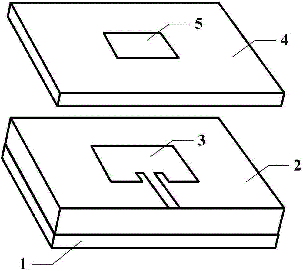
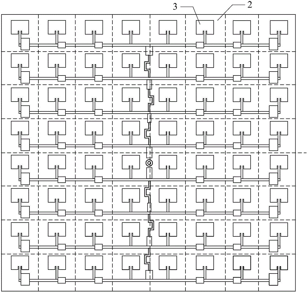
[0020] Specific embodiment one: combination Figure 1 to Figure 6 To illustrate this embodiment, the broadband sidelobe microstrip antenna array used in the collision avoidance radar system in this embodiment includes M×N antenna elements; M×N antenna elements form M rows and N columns. Rectangular array

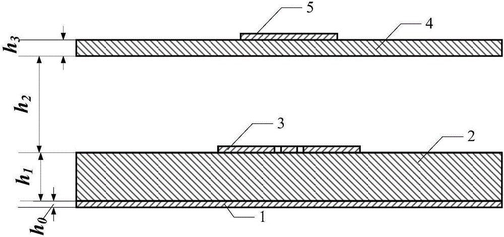
[0021] Each antenna unit includes a floor layer 1, an active radiation microstrip unit layer and a coupled radiation microstrip unit layer; the active radiation microstrip unit layer is fixed on the floor layer 1; the coupled radiation microstrip unit layer is suspended on the active radiation microstrip unit layer Above

[0022] The active radiation microstrip unit layer includes a lower substrate 2 and a first antenna array element 3, and the first antenna array element 3 is fixed inside the lower substrate 2;

[0023] The coupled radiation microstrip unit layer includes an upper substrate 4 and a second antenna array element 5, and the second antenna array element 5 is fixed i...

specific Embodiment approach 2

[0035] Specific implementation manner two: combination Figure 7 To explain this embodiment, this embodiment further defines the broadband low sidelobe microstrip antenna array used in the collision avoidance radar system described in the first embodiment. In this embodiment, the first antenna array element 3 includes No. 1 patch and No. 2 patch, the No. 1 patch is rectangular with a rectangular notch on one side of the rectangle, the No. 2 patch is also rectangular, and one end of the No. 2 patch is fixed at one end. No. patch in the rectangular gap.

[0036] Figure 7 The structural parameters of the active radiation microstrip unit layer in the medium are shown in Table 3.

[0037] Table 3 Description of the structural parameters of the active radiation microstrip unit layer

[0038]

[0039] Among them, L is the length of the lower substrate 2, W is the width of the lower substrate 2, La is the length of the first patch, Wa is the width of the first patch, Li is the length of...

specific Embodiment approach 3

[0040] Specific implementation mode three: combination Picture 8 To explain this embodiment, this embodiment further defines the broadband low sidelobe microstrip antenna array used in the collision avoidance radar system described in the first embodiment. In this embodiment, the second antenna element 5 is Rectangular patch.

[0041] Picture 8 The structural parameters of the middle coupling radiation microstrip unit layer are shown in Table 4.

[0042] Table 4 Description of the structural parameters of the coupled radiation microstrip unit layer

[0043]

[0044] Wherein, Lc is the length of the upper substrate 4, Wc is the width of the upper substrate 4, Lp is the length of the second antenna element 5, and Wp is the width of the second antenna element 5.


PUM


Abstract

The invention provides a broadband low-sidelobe microstrip antenna array for an anti-collision radar system, relates to a broadband antenna device for the anti-collision radar system, and aims at solving the problems of a narrow working band and a low gain of the broadband low-sidelobe microstrip antenna array. The broadband low-sidelobe microstrip array antenna comprises M*N antenna units, wherein each antenna unit comprises a floor layer, an active radiation microstrip unit layer and a coupled radiation microstrip unit layer; the active radiation microstrip unit layer is fixed on the floor layer; the coupled radiation microstrip unit layer is suspended above the active radiation microstrip unit layer; the active radiation microstrip unit layer comprises a lower substrate and a first antenna array element; the coupled radiation microstrip unit layer comprises an upper substrate and a second antenna array element; the M*N antenna units are fixedly connected in a microstrip line feeding manner; and finally feeding is carried out with a coaxial line of which the characteristic impedance is 50 omega. The broadband low-sidelobe microstrip array antenna has the beneficial effects of being light in weight, easy to integrate, high in gain, low in sidelobe and small and is suitable for the anti-collision radar system in various occasions.

Description

Technical field [0001] The invention relates to a broadband antenna device of an anti-collision radar system. Background technique [0002] With the development of wireless communication technology and the popularization and application of wireless products, especially the advancement of ultra-wideband wireless communication technology in recent years, people’s research on broadband antennas tends to be more large-scale, small-sized, efficient and easy to install. Claim. Among the many antenna types that can meet the aforementioned requirements, microstrip antennas have received widespread attention due to their low cost, light weight, easy processing, and easy mass production. However, the traditional microstrip antenna unit operating frequency band covers Low frequency and small gain cannot meet people's needs. In wireless communication, a certain number of antennas are more commonly used to form an array. When the feed network of the antenna and the microstrip radiating ele...

Claims


Application Information

Patent Timeline
Patent Type & Authority Applications(China)
IPC IPC(8): H01Q1/38H01Q1/50H01Q21/06
CPCH01Q1/38H01Q1/50H01Q21/0075H01Q21/065
Inventor 林澍刘冠君王蕾赵志华张雨薇
Owner HARBIN INST OF TECH
Why Eureka
Try Eureka