Feeding structure for waveguide slot frequency scanning antenna

A technology of waveguide slots and frequency sweeping, applied in slot antennas, antennas, antenna arrays, etc., to achieve high efficiency, compact and reasonable structure, and high feeding efficiency

Active Publication Date: 2016-07-20
ANHUI SUN CREATE ELECTRONICS
View PDF3 Cites 0 Cited by
  • Summary
  • Abstract
  • Description
  • Claims
  • Application Information

AI Technical Summary

Problems solved by technology

At present, the conventional frequency scanning antenna can only realize the requirements of vertical polarization characteristics, that is, the above structure can only realize the microwave gu...

Method used


Image

  • Feeding structure for waveguide slot frequency scanning antenna
  • Feeding structure for waveguide slot frequency scanning antenna
  • Feeding structure for waveguide slot frequency scanning antenna

Examples


Embodiment 1

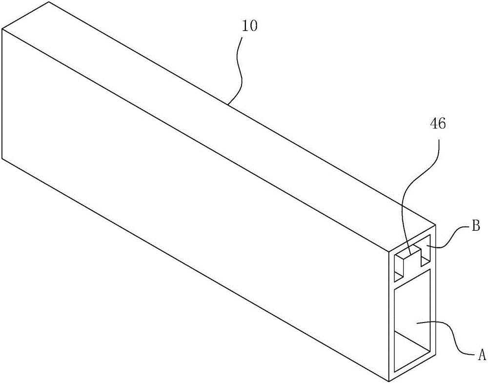
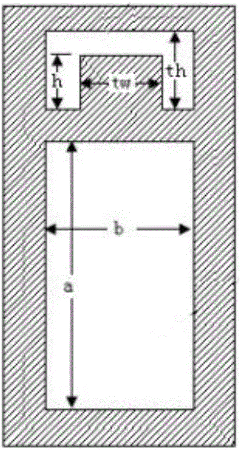
[0040] see figure 2 , the power feed port A is the signal input port, and the first coupling port B is on the same side as the power feed port A; image 3 Dimension drawings for its side view. Depend on image 3 From the middle point of view, the cavity where the cross section of the lower layer is located is a rectangular waveguide layer, where the wide side a=12.95mm and the narrow side b=6.48mm. The cavity where the upper cross-section is located is the ridge waveguide layer, which shares the narrow wall with the rectangular waveguide layer, so the width of the ridge waveguide layer b=6.48mm, the height of the ridge waveguide layer th=4.04mm, the width of the ridge block tw=3.12mm, and the ridge block Height h=2.56mm. And the port size of the other end of the present invention is as Figure 5 As shown, the size of the second coupling port C is exactly the same as that of the first coupling port B, and the size of the feed port A is exactly the same as that of the throu...

Embodiment 2

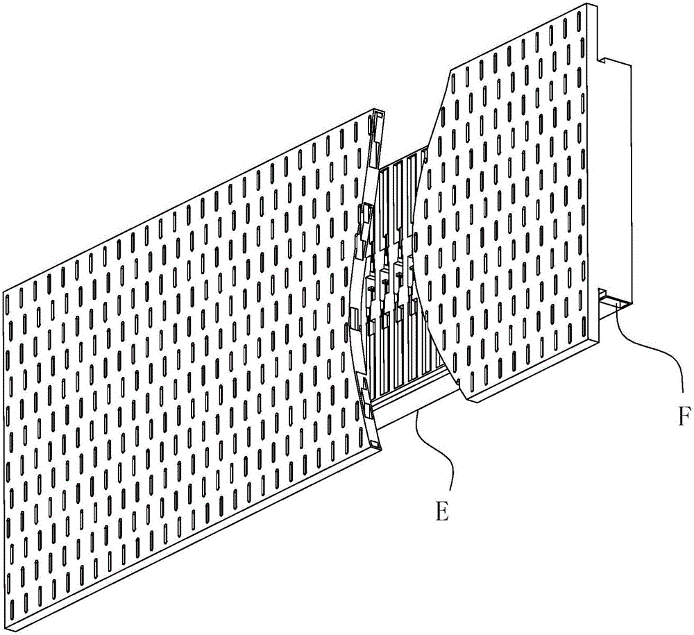
[0052] see figure 1 , is a schematic diagram of the structure of the 42×12 waveguide slot frequency-swept antenna operating in the Ku band of the present invention. In this embodiment, the ridge waveguide wide-side slot antenna is selected as the external radiation antenna, and each column is a 12-element resonant standing wave array. Wherein the feeding structure E formed by the parallel arrangement of the present invention is the same as the feeding structure described in Embodiment 1 in structural appearance and working principle, and the size selection method, range, working principle, etc. of the feeding structure with different coupling coefficients can be implemented by Example 1 and the preceding text are obtained through further data optimization, and will not be described in detail here. When working, the input signal of the antenna is fed through the input port F of the feed network at one end, and the output signal is connected to a matching load through the outpu...


PUM

PropertyMeasurementUnit
Heightaaaaaaaaaa
Widthaaaaaaaaaa

Abstract

The invention belongs to the technical field of panel antennae, and particularly relates to a feeding structure for a waveguide slot frequency scanning antenna. The feeding structure comprises a tube wall member. A transverse baffle plate is configured in the tube chamber of the tube wall member, thereby forming a double-layer chamber wall structure in which the upper layer is a ridge waveguide layer and the lower layer is a rectangular waveguide layer. A metal diaphragm is configured in the rectangular waveguide layer. The top wall of the rectangular waveguide layer is provided with a coupling window. The ridge waveguide layer is composed of a left ridge waveguide layer and a right ridge waveguide layer which are configured in axis symmetry. In the signal advancing path of the wedge waveguide layer, the side wall of the left ridge waveguide and the side wall of the right ridge waveguide respectively have a five-segment stepped chamber structure. The ridge waveguide further comprises ridge blocks and foreign-shaped branches. The feeding structure has advantages of more compact and smaller structure, and lower working loss. Furthermore purposes of horizontal polarization characteristic conversion and vertical polarization characteristic conversion are realized according to the requirement. Overall efficiency and application range of an antenna array can be further improved.

Description

technical field [0001] The invention belongs to the technical field of planar antennas, and in particular relates to a feeding structure for waveguide slot frequency-sweep antennas. Background technique [0002] In various wireless communication and radar systems, the transmission and reception of information depends on the antenna. With the rapid development of modern large-capacity, multi-functional, ultra-broadband integrated information systems, the number of information subsystems carried on the same platform has greatly increased, and the number of antennas required has also increased accordingly. This is in line with the requirement to reduce the overall cost of integrated information systems, The development trends of reducing weight, reducing the radar cross section of the platform, and achieving good electromagnetic compatibility characteristics are contradictory. For the above situation, the multi-polarized antenna can effectively solve this problem, and it can d...

Claims


Application Information

Patent Timeline
IPC IPC(8): H01Q21/00H01Q13/10
CPCH01Q13/10H01Q21/00
Inventor 胡卫东赵继明夏义全
Owner ANHUI SUN CREATE ELECTRONICS
Why Eureka
Try Eureka