Ignition device
一种点火装置、点火线圈的技术,应用在其他装置、点火控制器、发动机点火等方向,能够解决火花塞电极消耗、火花放电熄灭、点燃稳定性紊乱等问题,达到点燃稳定化、简单结构、可靠性高的效果
- Summary
- Abstract
- Description
- Claims
- Application Information
AI Technical Summary
Problems solved by technology
Method used
Image

Examples
no. 1 approach
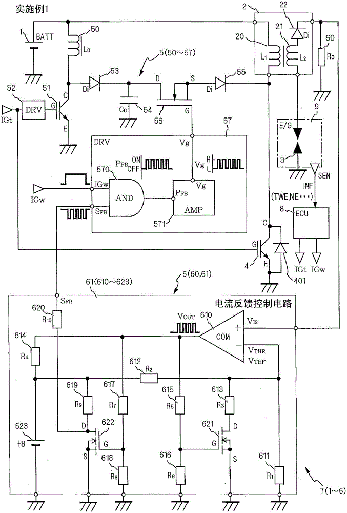
[0046] refer to figure 1 An outline of the ignition device 7 according to the first embodiment of the present invention will be described. It should be noted that, in the description of this application document, the positive and negative signs represent the direction of the current, so the magnitude of the current is represented on the basis of the magnitude of the absolute value, and the increase or rise of the current indicates that the absolute value of the current increases. , the decrease or decrease of the current indicates that the absolute value becomes smaller.
[0047] The ignition device 7 of the present invention is provided in each cylinder of the internal combustion engine 9, and causes a spark discharge to ignite a mixed gas of fuel and air introduced into a combustion chamber (not shown).
[0048]The ignition device 7 includes a DC power supply 1 , an ignition coil 2 , a spark plug 3 , an ignition switch 4 , an auxiliary power supply 5 , and a secondary curre...
no. 2 approach
[0165] refer to Image 6 The ignition device 7b according to the second embodiment of the present invention will be described.
[0166] In addition, the structure similar to the said embodiment is abbreviate|omitted, and only the structure of the feedback control mechanism 6b and the drive driver 57b which are characteristic of this embodiment is shown.
[0167] In Example 1, the output V using the comparator is shown OUT The threshold switching switch 621 is driven to change the voltage input to the inverting input (-) to generate hysteresis. On the other hand, in the present embodiment, the secondary current detection voltage V is input to the inverting input (-). I2 , the control voltage +B of the control power supply 623 is proportionally distributed by the voltage dividing resistors 611b and 612b and input to the non-inverting input (+). In addition, the present embodiment is different in that hysteresis is formed by restoring the output Vout of the comparator 610 thro...
no. 3 approach
[0171] refer to Figure 7 The ignition device 7c according to the third embodiment of the present invention will be described.
[0172] The present embodiment is different in that, in addition to the configuration of the above-described embodiment, the secondary current feedback control means 6c includes a secondary current feedback control circuit 61c and a discharge extinguishing detection means IG F U62 , secondary current command value calculation mechanism 63 and secondary current learning mechanism 64 . Discharge extinguishing detection mechanism IG F U62 detects the presence or absence of secondary current I caused by the air flow in the cylinder flowing in the combustion chamber 2 The discharge is extinguished, and the discharge extinguishing signal IG is sent F . The secondary current command value calculation means 63 calculates the target secondary current value I based on the operating conditions 2 I. The secondary current learning means 64 corrects the targe...
PUM
 Abstract
Description
Claims
Application Information
 - R&D
- Intellectual Property
- Life Sciences
- Materials
- Tech Scout
- Unparalleled Data Quality
- Higher Quality Content
- 60% Fewer Hallucinations
Browse by: Latest US Patents, China's latest patents, Technical Efficacy Thesaurus, Application Domain, Technology Topic, Popular Technical Reports.
© 2025 PatSnap. All rights reserved.Legal|Privacy policy|Modern Slavery Act Transparency Statement|Sitemap|About US| Contact US: help@patsnap.com