
An injection-molded flushing channel for an all-plastic toilet

An injection molding, toilet technology, applied in flushing toilets, water supply devices, urinals, etc., can solve problems such as low work efficiency, achieve high flushing efficiency, suitable shape, and overcome the effects of water leakage

Active Publication Date: 2018-06-29
AIMBON (CHENGDU) ELECTRIC APPLICANCE CO LTD
View PDF6 Cites 0 Cited by
  • Summary
  • Abstract
  • Description
  • Claims
  • Application Information

AI Technical Summary

Problems solved by technology

The upper and lower shells are connected by welding and gluing. The work efficiency is low, and the plastic buckle is connected with the sealing strip. Because the plastic buckle can become loose under the action of stress for a long time, water leakage occurs from time to time.

Method used


Image

  • An injection-molded flushing channel for an all-plastic toilet
  • An injection-molded flushing channel for an all-plastic toilet
  • An injection-molded flushing channel for an all-plastic toilet

Examples


Embodiment 1

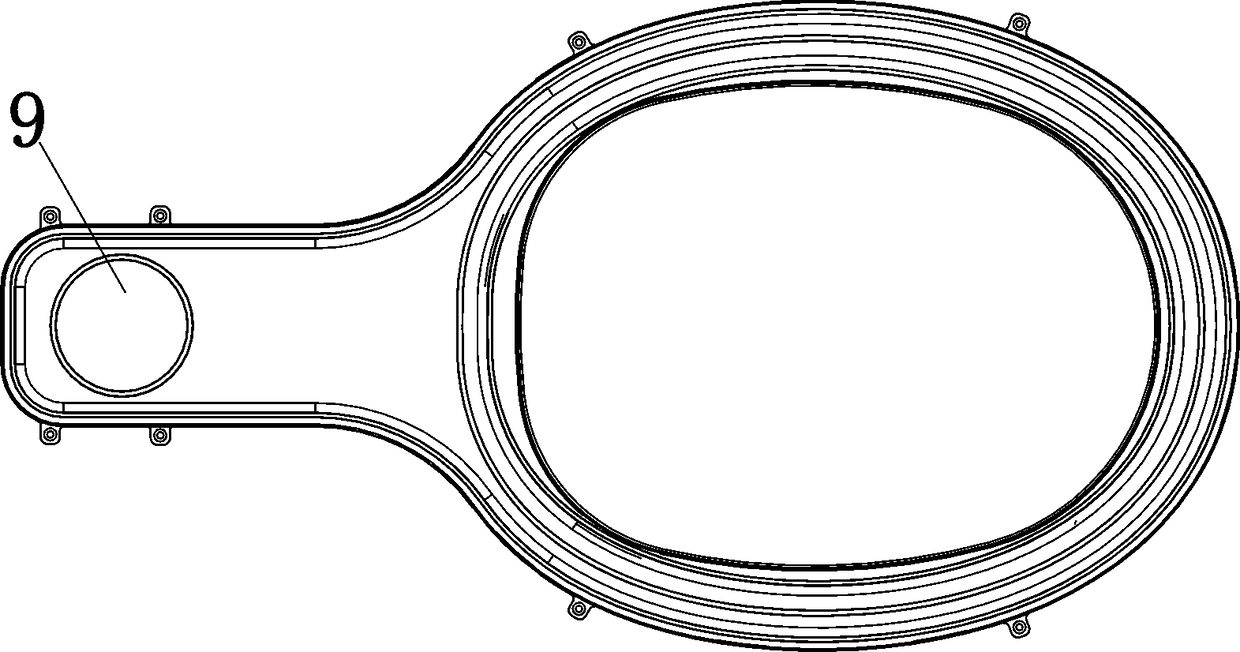
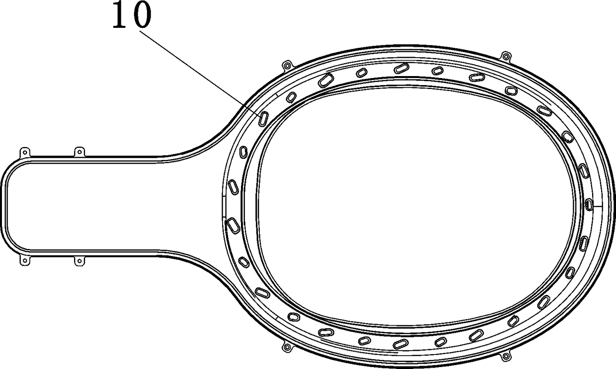
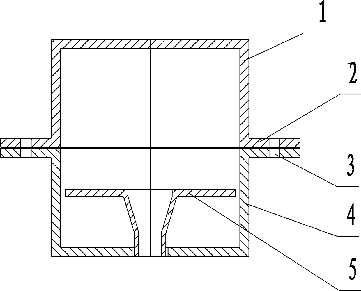
[0037] Embodiment 1: the first step, form the upper shell, the lower shell, and the flushing nozzle plate installed in the lower shell respectively with the injection molding process, see figure 1 , figure 2 , image 3 . The materials used are all polypropylene. In the second step, after the above three parts are matched and aligned, they are placed in the injection mold cavity of the horizontal U-shaped inner and outer rings, and injection molded again to form the inner and outer rings connecting the upper shell and the lower shell Horizontal U-shaped enclosure. The flanges of the upper and lower shells are embedded in the U-shaped grooves, and the surrounding bars have plastic rivets with a diameter of about 1.5mm that penetrate up and down in the vertical direction every 30-50mm. See Figure 4 . The fence material is ABS. After the two-step process, the flushing channel components are completed without post-processing.

Embodiment 2

[0038] Embodiment 2: With reference to Embodiment 1, the difference is that the lower shell and the flushing nozzle plate installed in the lower shell are formed into an integral part at one time, that is, the first step is to mold the upper shell respectively with the injection molding process. The lower housing of the flushing nozzle. In the second step, after the above-mentioned two parts are matched and aligned, the inner and outer ring horizontal U-shaped enclosures for connection are formed by injection molding. Compared with Embodiment 1, the mold structure of the lower housing with the flushing nozzle is more complicated, but the workload of separately forming the flushing nozzle plate can be reduced.


PUM

PropertyMeasurementUnit
heightaaaaaaaaaa
diameteraaaaaaaaaa

Abstract

The invention discloses an injection molding flushing waterway for an all-plastic closestool. The injection molding flushing waterway is characterized in that a flushing waterway component is composed of a flushing waterway upper shell and a flushing waterway lower shell which are manufactured through an injection moulding process, a flushing nozzle plate mounted in the lower shell and a U-shaped inner ring round bar and a U-shaped outer ring round bar which are connected with the upper shell and the lower shell; by the implementation of the injection molding flushing waterway, arrangement, the number and the shape of flushing guide holes are proper, and cleaning water flow maintains the turbulent state in a flushing flowing channel and also maintains a certain angle with an inner container so that it can be convenient to wash the closestool, therefore flushing efficiency is high, flushes tests are conducted with hollow plastic balls universal in the industry, and flushed out balls are 20% more than the standard. The horizontal U-shaped inner ring annular round bar and the horizontal U-shaped outer ring annular round bar are connected with the upper shell and the lower shell of the flushing waterway, turned edges of the upper shell and the lower shell are embedded into U-shaped grooves, besides, in the injection molding process of round strips, plastic melt flows into through holes in the turned edges of the shells, a plurality of plastic rivets are formed, connection is reliable, the phenomenon of water leakage possibly occurring in an original process is overcome, and the postprocessing process is omitted.

Description

technical field [0001] The invention relates to the production field of sanitary ware, in particular to a thermoplastic flushing channel for an all-plastic water closet manufactured by an injection molding process and a production method. Background technique [0002] In the sanitary ware manufacturing industry, ceramics are traditionally used to make toilets. Toilets made of ceramics have the advantages of acid and alkali corrosion resistance, high surface hardness, friction resistance, and scratch resistance, but they also have disadvantages such as heavy transportation and installation, and fragility. From the perspective of environmental protection, the production process of ceramics also pollutes the environment with emissions, and waste ceramic toilets cannot be recycled and are difficult to deal with. In addition, the production process of toilets made of ceramics is complicated, the ceramic sintering process consumes a lot of energy, pollutes the environment to a cer...

Claims


Application Information

Patent Timeline
Patent Type & Authority Patents(China)
IPC IPC(8): E03D11/13B29C45/14
CPCB29C45/14467E03D11/13E03D2201/40
Inventor 皮体斌孔文艺
Owner AIMBON (CHENGDU) ELECTRIC APPLICANCE CO LTD
Learn More