Space module building

A technology of space and architecture, applied in the direction of architecture and building structure, can solve the problems of surplus, waste, warping and instability, etc.

Inactive Publication Date: 2016-07-27
宋启宽 +1
View PDF0 Cites 5 Cited by
  • Summary
  • Abstract
  • Description
  • Claims
  • Application Information

AI Technical Summary

Problems solved by technology

[0003] (1) Reinforced concrete structure: The column or shear wall section is hooped by the column or the shear wall's tendon to bulge due to vertical load extrusion, and the square stirrup obviously cannot fully exert the effect of preventing the concrete from bulging function, so that the waste caused by the inability to give full play to the maximum effect of various materials of reinforced concrete
[0004] (2) The columns of the steel structure also have the tendency of warping and instability caused by the compression of the slender rods due to the scattered arrangement, so the vertical bearing capacity of the steel column cannot be fully utilized, or in other words, the steel column needs to be enlarged Section
[0007] The reason for the high construction cost is the scattered layout of the load-bearing components mentioned above, and because each load-bearing component is not a cost-effective load-bearing structure, it cannot give full play to the role of materials, and each load-bearing component, There is excess bearing capacity or safety surplus and waste
[0008] The cost-effective concrete-filled steel tube column saves more than 60% compared with the reinforced concrete column section, but the construction of the structural joints is more troublesome, and the combination with the cast-in-place reinforced concrete shear wall is more troublesome, especially for residential buildings. So many load-bearing components in the building are replaced by cost-effective steel tube concrete columns

Method used


Image

  • Space module building
  • Space module building
  • Space module building

Examples


Embodiment

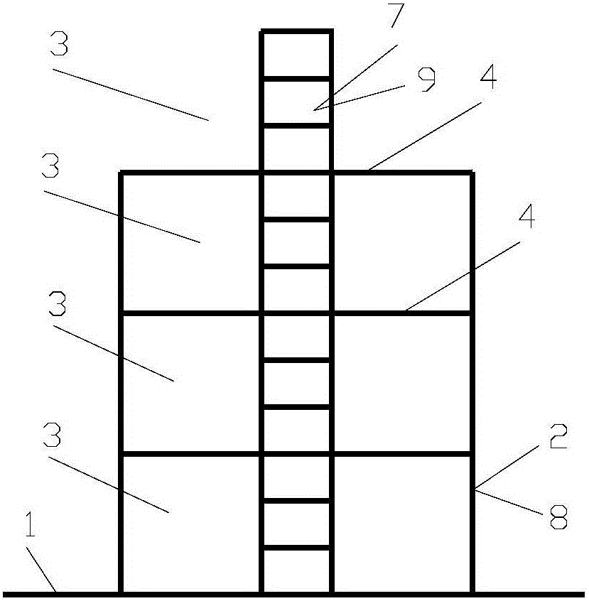
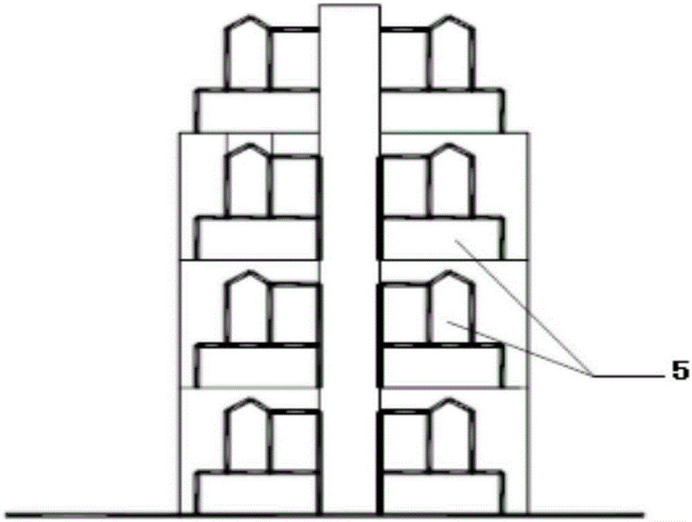
[0074] 1. If figure 1 , 2 As shown, a space module building includes a skeleton, a space module 3, and a built-in object 5; the construction method of the space module building includes the following steps:

[0075] (1) Build a basic structure such as a reinforced concrete basement under the ground;

[0076] (2) build the frame on the base structure;

[0077] (3) Build the built-in object 5 in the space module 3 .

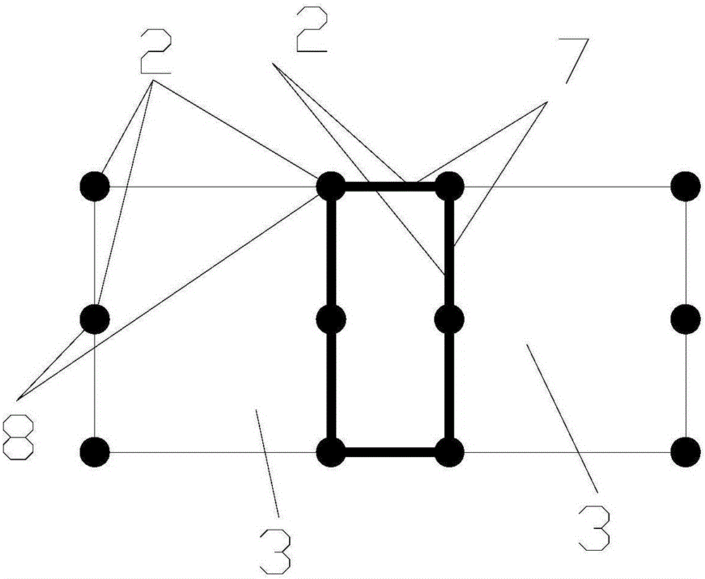
[0078] Such as figure 1 , 3 As shown, the skeleton includes vertical resistance members 2, floor structures 4, and protrusions 9;

[0079] The floor structure, arranged horizontally, is divided into three natural-story space modules 3 vertically distributed along the skeleton in the framework; the vertical resistance member 2, arranged vertically, is divided into Distributed Spatial Module 3;

[0080] The skeleton is fixedly connected by the vertical resistance member 2 and the floor structure 4 and the horizontal resistance member serving as the beam of the...


PUM


Abstract

The invention relates to a space module building which comprises a framework, space modules and contained objects of multi-storey buildings and the like.The framework comprises building roof structures, force-resisting components and optional protruding objects; the space modules are formed by dividing the framework through the horizontally arranged storey structures and the vertically distributed vertical force-resisting components, the height of each space module is the height of at least two natural storeys, the plane dimension is large, and the contained objects of the multi-storey buildings and the like can be built in the space modules; generally, concrete-filled steel tube columns are arranged on the outer edges of each space module, and the multiple space modules are connected and separated through barrels which are arranged in the center area of the building in the horizontal plane; due to the fact that completely assembled type lightweight storeys and wall boards which are low in price and high in heat-insulating property can be adopted as the contained objects of the multi-storey buildings and the like, compared with an existing high-rise building, the space module building is high in construction speed, reduces the construction cost and labor intensity, is greener and more environmentally friendly and improves the economic benefit of a construction project.

Description

technical field [0001] The invention relates to the field of buildings, in particular to a space module building. Background technique [0002] Most of the current buildings, especially residential buildings, use reinforced concrete structures except for a small amount of steel structures. Most of the floors are cast-in-place or laminated reinforced concrete structures. The common feature of existing buildings is that vertical load-bearing members such as vertical load-bearing columns or shear walls or frame shear wall structures are arranged as evenly as possible according to the building layout, and each vertical load-bearing member is arranged from bottom to top Bear most of the vertical load in the bearing area. The vertical bearing capacity of this structural system is worse than that of CFST columns because: [0003] (1) Reinforced concrete structure: The column or shear wall section is hooped by the column or the shear wall's tendon to bulge due to vertical load ex...

Claims


Application Information

Patent Timeline
Patent Type & Authority Applications(China)
IPC IPC(8): E04B1/02E04B1/18
CPCE04B1/02E04B1/18
Inventor 宋启宽宋戈
Owner 宋启宽
Why Eureka
Try Eureka