Energy-saving heat pump type intermediate-temperature spray evaporation system

A technology of spray evaporation and spray system, which is used in general water supply conservation, water/sewage treatment, water/sludge/sewage treatment, etc. It can solve the problems of increased heat dissipation, manual cleaning, inconvenient operation, etc., and achieve compact equipment. , high flexibility, small footprint

Active Publication Date: 2016-08-03
上海胜丰环境能源科技有限公司
View PDF9 Cites 3 Cited by
  • Summary
  • Abstract
  • Description
  • Claims
  • Application Information

AI Technical Summary

Problems solved by technology

[0003] The single-circulation system heat pump evaporation technology is also called MVR evaporation technology. Its principle is to use a water vapor compressor to compress the secondary water vapor generated by evaporation into high-temperature and high-pressure water vapor, and continue to evaporate the mother liquor as a heat source again; its characteristics are, Due to the use of a single cycle system, its energy consumption is low. The overall equipment cooling efficiency COP is generally 18-20, and the energy consumption is about 31-35

Method used


Image

  • Energy-saving heat pump type intermediate-temperature spray evaporation system

Examples


Embodiment Construction

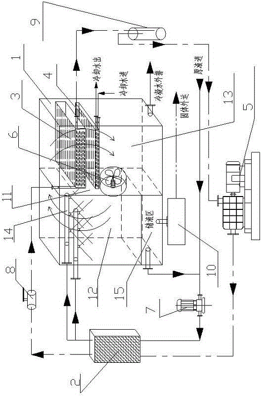
[0021] like figure 1 As shown, an energy-saving heat pump medium-temperature spray evaporation system of the present technology includes an evaporation separation chamber 1, a condenser (refrigerant) 2, an evaporator (refrigerant) 3, a water cooler 4, a heat pump 5, an axial blower 6, and a circulating water pump 7 , Throttling device 8, gas-liquid separator / purifier 9, solid-liquid separator 10, partition 11, evaporation chamber 12, separation chamber 13, spray system 14, liquid storage area 15.

[0022] The evaporation and separation chamber 1 is divided into an evaporation chamber 12 and a separation chamber 13 by a partition 11. An axial blower 6 is installed in the middle of the partition 11 and a cold air inlet is left, and a hot air outlet is formed between the top of the partition and the inner wall of the evaporation and separation chamber; the evaporation chamber 12 The bottom is a liquid storage area 15, and the top is equipped with a spray system 14; the liquid sto...


PUM


Abstract

The invention discloses an energy-saving heat pump type intermediate-temperature spray evaporation system which comprises an evaporation and separation chamber, a condenser, an evaporator, a water cooler, a heat pump, an axial-flow blower, a circulating water pump, a throttling device and a gas-liquid separator/purifier. The interior of the evaporation and separation chamber is divided into an evaporation chamber and a separation chamber through a separation plate. The evaporation chamber and the separation chamber are communicated through a hot air outlet between the top of the separation plate and the evaporation and separation chamber. The axial-flow blower is mounted on the separation plate, a cold water inlet is reserved in the separation plate, and the hot air outlet is reserved in the top of the separation plate. A liquid storage area is arranged at the bottom of the evaporation chamber, and a spraying system is mounted at the top of the evaporation chamber. The liquid storage area of the evaporation chamber is connected with the spraying system at the top of the evaporation chamber through the circulating water pump and the condenser. The evaporator and the water cooler are sequentially arranged in the separation chamber from top to bottom. The evaporation chamber is connected with an air inlet of the heat pump through the gas-liquid separator/purifier. An air outlet of the heat pump is connected with the condenser. The condenser is connected with the evaporator through the throttling device. The system is small in occupied area, low in running cost, flexible and convenient to operate and suitable for being used and popularized.

Description

technical field [0001] The technology relates to an energy-saving heat pump type medium-temperature spray evaporation system, which belongs to the field of high-concentration refractory wastewater. Background technique [0002] For high-concentration refractory wastewater, the commonly used treatment process is the heat pump evaporation process. Heat pump evaporation technology can be divided into single cycle system and double cycle system. [0003] The single-cycle system heat pump evaporation technology is also called MVR evaporation technology. Its principle is to use a water vapor compressor to compress the secondary water vapor generated by evaporation into high-temperature and high-pressure water vapor, and continue to evaporate the mother liquor as a heat source again; its characteristics are, Due to the use of a single cycle system, its energy consumption is low. The overall equipment cooling efficiency COP is generally 18-20, and the energy consumption is about 31...

Claims


Application Information

Patent Timeline
IPC IPC(8): C02F1/12
CPCY02A20/141C02F1/12
Inventor 蒋程
Owner 上海胜丰环境能源科技有限公司
Why Eureka
Try Eureka