Laser projection device

A technology of laser projection and laser light source, applied in optics, optical components, instruments, etc., can solve the problems of unable to have image distortion and modulation function at the same time, image shifting function, undisclosed technical solutions, etc.

Inactive Publication Date: 2016-08-03
OPUS MICROSYSTEMS CORP
View PDF22 Cites 7 Cited by
  • Summary
  • Abstract
  • Description
  • Claims
  • Application Information

AI Technical Summary

Problems solved by technology

US8,107,147 uses two one-dimensional deflection elements to scan laser light into a two-dimensional image, wherein the deflection element or the final exit prism shares the base with the reflector that guides the light path, but the final exit prism only has a modulated image Distortion effects (see its Figure 7 -9 shown output optics 710 and its related descriptions), therefore, although US8,107,147 also adopts wedge-shaped optics (such as Figure 7 The output optical part 710 shown in -9), but it cannot have the image distortion modulation function and the image shifting function at the same time
In addition,

Method used


Image

  • Laser projection device
  • Laser projection device
  • Laser projection device

Examples


Embodiment Construction

[0042] In order to make the present invention more definite and detailed, the preferred embodiments are listed hereby in conjunction with the following diagrams, and the structure and technical characteristics of the present invention are described in detail as follows:

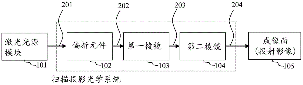
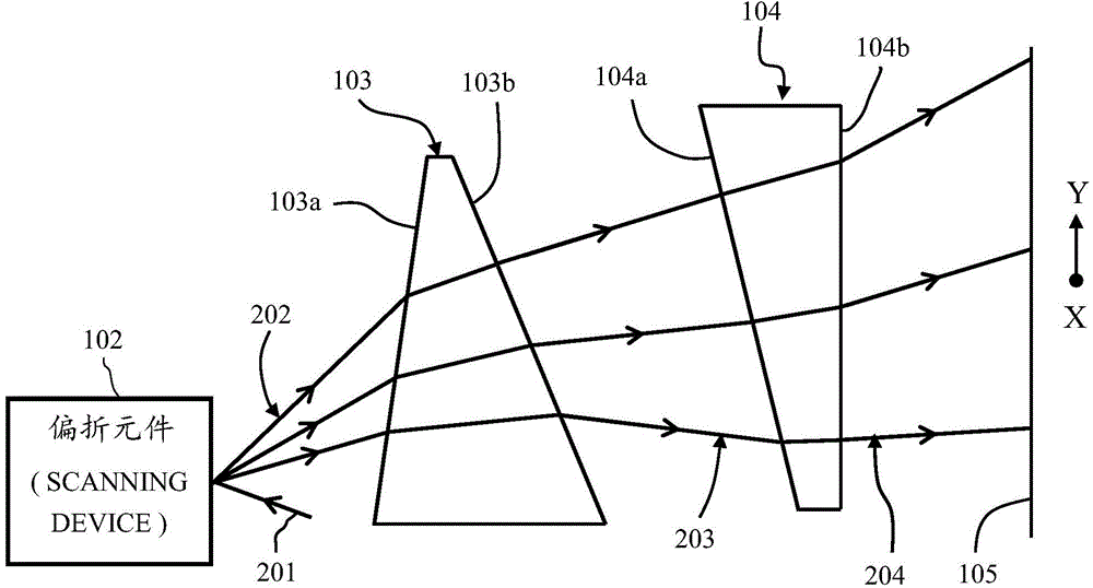
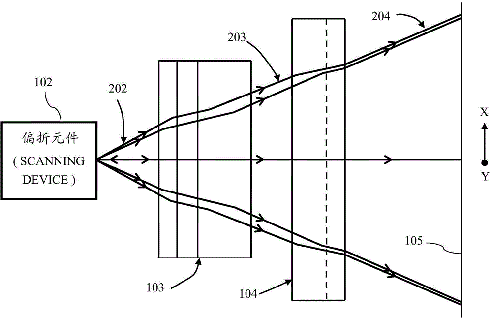
[0043] Such as figure 1 , figure 2 , image 3 As shown, they are respectively a schematic block diagram of the system architecture of the laser projection device provided by the present invention, a schematic diagram of a side (Y axis-slow axis scanning direction) and its top surface (X axis-fast axis scanning direction) of an embodiment. The laser projection device provided by the present invention sequentially includes along the beam propagation direction: a laser light source (module) 101, a deflection element (micro-electromechanical two-dimensional scanning galvanometer) 102, a first prism 103 and a second prism 104, Wherein the components such as the deflection element (micro-electromechanical two-d...


PUM


Abstract

The invention discloses a laser projection device, which comprises a laser source module, a deflection element, a first prism and a second prism, and is characterized in that the laser source module is used for generating an input beam to be fed to the deflection element, for example, fed to a reflector in a micro-electromechanical two-dimensional scanning galvanometer; the deflection element, such as a micro electromechanical two-dimensional scanning galvanometer, is used for enabling the input beam from the laser t source to deflect towards a first scanning direction and a second scanning direction, which are orthogonal to each other so as to form a scanning beam; the first prism is used for enabling the scanning beam from the deflection element to be able to be incident from an incident surface of the first prism and penetrate through the first prism and be emitted from an emergent surface of the first prism; and the second prism is used for enabling the scanning beam emitted from the emergent surface of the first prism to be incident from an incident surface of the second prism and penetrate through the second prism and be emitted from an emergent surface of the second prism so as to perform two-dimensional scanning on an imaging surface to form an image, wherein a specific condition can be met through a relative relation of an angle between the first prism and the second prism, thereby achieving the effects of image distortion modulation and image moving and lifting at the same time.

Description

technical field [0001] The present invention relates to a laser projection device, in particular to a scanning optical path between the deflection element (micro-electromechanical two-dimensional scanning galvanometer) and the imaging surface of scanning projection, which is sequentially arranged from the galvanometer to the imaging surface. A prism and a second prism, and the relative relationship between the angles of the first prism and the second prism can meet specific conditions, so that the image frame scanned and projected on the imaging surface can simultaneously have the image distortion modulation function and the image Lift function. Background technique [0002] The projection method using a single light spot for two-dimensional scanning, such as feeding the incident light beam off-axis to the MEMS scanning mirror to scan the outgoing light beam, needs to consider the problems of image distortion correction and screen shifting at the same time. The above-mentio...

Claims


Application Information

Patent Timeline
IPC IPC(8): G02B26/10
Inventor 洪昌黎叶逢春刘裕升
Owner OPUS MICROSYSTEMS CORP
Why Eureka
Try Eureka