Construction technology of section assembled box girder erection based on descending bridge erecting machine

A construction technology and bridge erecting machine technology, applied in bridge construction, bridge, erection/assembly of bridges, etc., can solve the problems of high pier body structure requirements, poor visibility, low stability, etc.

Active Publication Date: 2017-12-19
CHINA RAILWAY FIRST GRP CO LTD
View PDF5 Cites 2 Cited by
  • Summary
  • Abstract
  • Description
  • Claims
  • Application Information

AI Technical Summary

Problems solved by technology

Compared with the downward type bridge erecting machine, the upward type bridge erection machine has the advantages of no need to lay running tracks, large lifting height, and convenient installation. However, the upward type bridge erection machine has the following defects: First, the overall installation height is high and stable Second, the requirements for the substructure of the bridge are high, specifically for the pier body structure of the bridge to be constructed, so as to meet the requirements of stability and support; third, the erection process is relatively complicated, and the pier needs to be installed in advance The top beam should be transported backwards, and the assembly sequence of the head and tail spans should be considered; fourth, the visibility of the girder section assembly process of the upward bridge erecting machine is poor, the assembly accuracy is not easy to control, and the linear adjustment is difficult

Method used


Image

  • Construction technology of section assembled box girder erection based on descending bridge erecting machine
  • Construction technology of section assembled box girder erection based on descending bridge erecting machine
  • Construction technology of section assembled box girder erection based on descending bridge erecting machine

Examples


Embodiment Construction

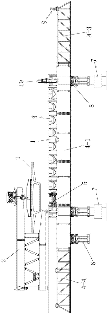
[0123] Such as Figure 17 The construction process of segmental assembled box girder erection based on the down-going bridge erecting machine is shown. The down-going bridge erecting machine is used to erect the constructed box girder. A plurality of box girder segments 1 are assembled from the back to the front, and each hole beam of the constructed box girder is supported by two front and rear piers 7, that is, the front and rear ends of each hole beam are respectively supported by a bridge pier 7;

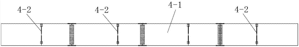
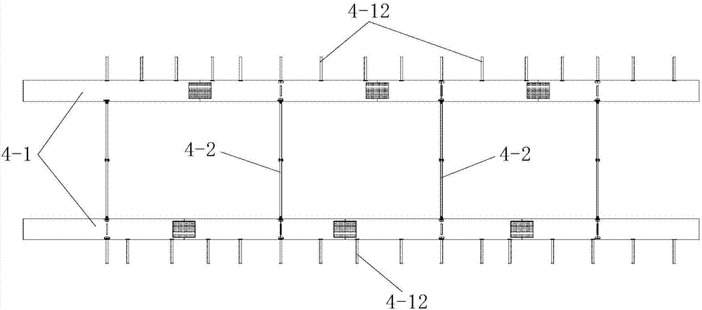
[0124] Such as figure 1 As shown, the descending bridge erecting machine includes a bottom horizontal support system, a main girder system installed on the bottom horizontal support system, a longitudinal movement system for moving the main girder system longitudinally, and a box girder section Section 1 is hoisted to the cantilever crane 2 on the main girder system, an assembly frame 3 for assembling the multiple box girder segments 1 hoisted on the main girder system, and an ...


PUM


Abstract

The invention discloses a construction process for segmental assembled box girder erection based on a descending bridge erecting machine. The descending bridge erecting machine is used to erect the constructed box girder. The descending bridge erecting machine includes a bottom horizontal support system, a main girder System, longitudinal moving system, cantilever crane, assembly frame and assembly vehicle; during the construction of the box girder erection facilities, the construction of each hole beam of the constructed box girder is carried out along the longitudinal bridge direction from back to front. The process is as follows: 1. Construction of the first hole beam erection: installation of the main structure of the bridge erecting machine, hoisting of box girder segments and assembly of box girder segments; Second, construction of the next hole beam erection: the main structure of the bridge erecting machine moves forward to cross the hole, the cantilever crane moves forward, Box girder segment hoisting and box girder segment assembly; 3. Repeat step 2 until the erection process of the constructed box girder is completed. The invention has the advantages of simple process steps, reasonable design, convenient construction, easy control of the construction process, good use effect, simple and rapid completion of the box girder erection construction process, and easy guarantee of construction quality.

Description

technical field [0001] The invention belongs to the technical field of bridge construction, and in particular relates to a construction process for segmentally assembled box girder erection based on a descending bridge erecting machine. Background technique [0002] With the development of society, the bridge construction technology is not only innovating, the segmental assembled box girder construction has gradually become a kind of construction due to its advantages of fast construction speed, high degree of industrialization, high degree of automation, improved labor efficiency and strong environmental adaptability. The new construction technology, and the erection accuracy requirements of segmental assembled box girders are also greatly improved. [0003] The Second Wuhu Yangtze River Highway Bridge starts from Shijian, Wuwei County, Wuhu City, connects the North Yanjiang Expressway, passes through Cangtou and Dougou, crosses the Yangtze River at Jitou Mountain, ends at ...

Claims


Application Information

Patent Timeline
Patent Type & Authority Patents(China)
IPC IPC(8): E01D21/06
CPCE01D21/06
Inventor 静国锋陈伟杨学成张磊黄瑞忠师忠盼林俊安马祖桥孙晓义田晓东鲁伟闫永涛
Owner CHINA RAILWAY FIRST GRP CO LTD
Why Eureka
Try Eureka