Sliding chute and crankshaft linked engine transmission mechanism

A technology of transmission mechanism and engine, applied in the direction of machine/engine, transmission device, mechanical equipment, etc., can solve the problems of reducing piston work efficiency, increasing uneven friction and impact, accelerating cylinder wall, etc., to achieve power transmission and movement mode. Reasonable conversion, reduce vibration and noise, avoid the effect of lateral friction

Inactive Publication Date: 2016-08-10
安里千
View PDF6 Cites 6 Cited by
  • Summary
  • Abstract
  • Description
  • Claims
  • Application Information

AI Technical Summary

Problems solved by technology

[0005] 2. When the gas in the cylinder is ignited, the axial force of the gas pressure along the connecting rod is decomposed into a tangential force perpendicular to the radius of the crankshaft and a normal force along the radius. The tangential force obtained after the gas pressure is decomposed is much smaller than the acting The gas pressure on the piston, the engine output torque is equal to the product of the tangential force and the radius of the crankshaft, so the torque output by the tangential force of the crankshaft is much smaller than the torque directly converted by the gas pressure acting on the piston. The above analysis shows that the crankshaft The conversion efficiency of the connecting rod mechanism to convert linear reciprocating motion into uniform circular motion is low, that is, the gas pressure outputs useful power through the crankshaft connecting rod mechanism.
[0006] 3. The swing of the connecting rod in the existing crankshaft and connecting rod mechanism causes the gas pressure acting on the piston to generate a lateral pressure acting vertically on the cylinder wall, and the lateral pressure acting on the cylinder wall causes a large lateral force between the piston and the cylinder wall. Friction not only reduces the working efficiency of the piston, but also accelerates the wear of the cylinder wall, resulting in "jamming" and making the piston unable to work;
[0007] 4. The inertial force caused by the unbalanced rotary mass and rotary motion caused by the swing of the connecting rod in the crankshaft connecting rod mechanism not only affects the output power of the engine, but also makes the engine generate greater vibration and noise;
[0008] 5. The swing of the existing crankshaft and connecting rod causes alternating impact force between the piston and the cylinder wall and the rotating contact surface, which increases the uneven friction and impact between the various components, such as the phenomenon of knocking and pulling the cylinder that occurs from time to time. affect engine performance;
[0009] 6. Due to the swing of the crankshaft and connecting rod, the piston must be set with a longer piston skirt guide
[0010] In order to overcome the defects of the above-mentioned crankshaft-connecting rod mechanism engine, many people have tried to develop a conversion mechanism that replaces the crankshaft-connecting rod mechanism from reciprocating linear motion to circular motion. At present, there is no practical conversion mechanism that can replace the crankshaft connecting rod mechanism of the engine. rod mechanism

Method used


Image

  • Sliding chute and crankshaft linked engine transmission mechanism
  • Sliding chute and crankshaft linked engine transmission mechanism
  • Sliding chute and crankshaft linked engine transmission mechanism

Examples


Embodiment Construction

[0039] specific implementation plan

[0040] The specific implementation of the engine transmission mechanism in which the chute is linked with the crankshaft provided by the present invention will be described in detail below with reference to the accompanying drawings.

[0041] The structure of the first embodiment of the present invention is as follows:

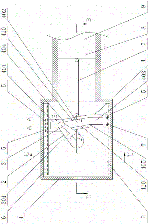
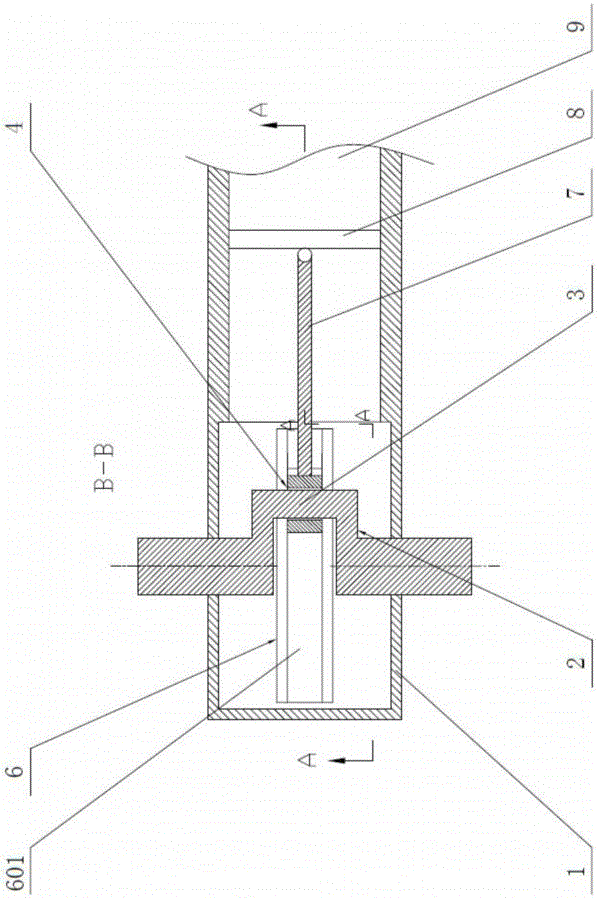
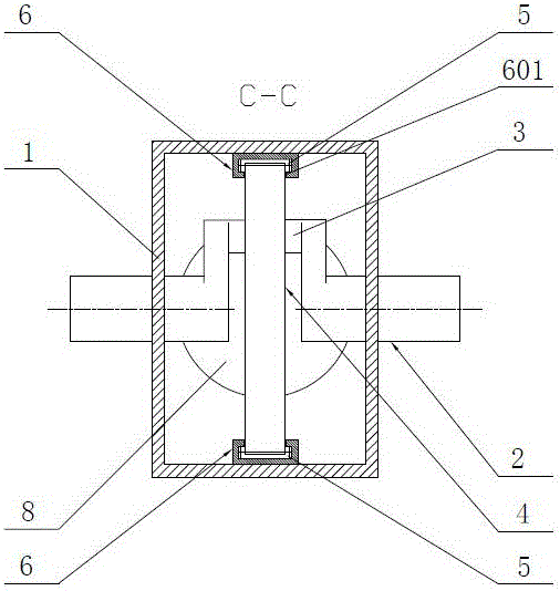
[0042] like figure 1 , 2 , 3, the crankshaft 2 is installed on the front and rear side walls of the housing 1, the distance from the axis of the crankshaft 2 to the axis of the journal 3 of the crankshaft 2 is the radius of rotation 301 of the journal 3, and the connecting rod chute closed at both ends 4 is set on the journal 3, the width of the connecting rod chute 4 is equal to the diameter of the journal 3, the two ends of the connecting rod chute 4 are provided with drag-reducing rollers 5, and the upper and lower inner walls of the housing 1 are respectively provided with shape In the same guide chute 6, the drag r...


PUM


Abstract

An engine transmission mechanism in which the chute is linked with the crankshaft Abstract An engine transmission mechanism in which the chute is linked with the crankshaft includes: the crankshaft 2 is installed on the front and rear side walls of the housing 1, and the connecting rod chute 4 with both ends closed is set in the On the journal 3 of the crankshaft 2, drag-reducing rollers 5 are set at both ends of the connecting rod chute 4, and guide chute 6 with the same shape are respectively set on the upper and lower inner walls of the housing 1, and the drag-reducing rollers 5 They are respectively placed in two parallel guide chutes 6, and the groove sides on one side or both sides of the connecting rod chute 4 are respectively connected to a plurality of connecting rods 7 and the pistons 8 in each cylinder 9 to form a single cylinder or multiple cylinders. Cylinder engine block. The transmission mechanism of the invention not only improves the output torque of the engine, but also eliminates the side pressure of the piston 8 on the cylinder wall of the cylinder 9, thereby improving the conversion efficiency of the engine.

Description

technical field [0001] The invention relates to a mechanical device for converting the reciprocating linear motion of the piston of an engine into a rotary motion, in particular to a conversion mechanism for the linkage between a chute and a crankshaft and a connecting rod, which replaces the existing crankshaft (handle)-connecting rod conversion mechanism. Background technique [0002] In mechanical engineering, such as piston engines, compressors and other machines that need to convert between linear reciprocating motion and circular motion, crankshaft (crank) connecting rod mechanism is generally used at present. [0003] The design and manufacture of the traditional crankshaft (handle) connecting rod mechanism has been very perfect, but there are obvious defects in both theoretical analysis and practical application: [0004] 1. The conversion efficiency of the existing crankshaft (handle) connecting rod mechanism is low. The geometric mechanism of the crankshaft (handl...

Claims


Application Information

Patent Timeline
Patent Type & Authority Applications(China)
IPC IPC(8): F02B75/32F16H21/18
CPCF02B75/32F16H21/18
Inventor 安里千刘庆毛灵涛刘升贵王聪
Owner 安里千
Why Eureka
Try Eureka