Torch burning efficiency control device

A torch combustion and control device technology, applied in the direction of combustion method, combustion type, control combustion, etc., can solve problems such as inability to verify, low efficiency of torch combustion, safety and environmental risks, etc., to solve insufficient torch combustion and ensure safe combustion , The effect of improving the combustion efficiency of the torch

Inactive Publication Date: 2016-08-10
CHINA PETROLEUM & CHEM CORP +1
View PDF4 Cites 2 Cited by
  • Summary
  • Abstract
  • Description
  • Claims
  • Application Information

AI Technical Summary

Problems solved by technology

If the flaring efficiency is low, hydrocarbon flaring gas and acid gas cannot be completely combusted, and flammable and toxic gas clouds will be formed, which will bring safety and environmental risks to the refinery and its surroundings
At present, most flare systems in refineries have problems with low combustion efficiency, which is prone to the formation of toxic or flammable gas clouds. At the same time, the company lacks effective flare gas combustion efficiency testing technology on site. The high combustion efficiency promised by the supplier is due to the fact that the elevated flare is far from the ground. It cannot be verified, so it is impossible to accurately evaluate the pros and cons of the flare burner

Method used


Image

  • Torch burning efficiency control device

Examples


Embodiment

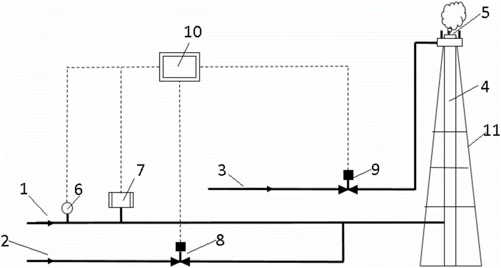
[0020] A torch combustion efficiency control device, such as figure 1 As shown, including the flare discharge pipeline 1, the flare discharge pipeline 1 is respectively connected with the flow meter 6, the gas composition analysis equipment 7 and the flare barrel 4, and the flow meter 6 and the gas composition analysis equipment 7 are all connected with the control system 10 , the control system 10 is connected to the steam pipeline 3 through the steam pipeline control valve 9, the steam pipeline 3 is connected to the flare burner 5, and the supplementary fuel gas pipeline 2 is respectively connected to the control system 10 and the flare discharge through the supplementary fuel gas pipeline control valve 8 The pipelines 1 are connected, and the torch burner 5 is set on the torch cylinder 4; the control system 10 has a built-in torch combustion efficiency model that has been simulated and tested through experiments, and the torch combustion efficiency model is associated with t...


PUM


Abstract

The invention relates to a torch burning efficiency control device. The torch burning efficiency control device comprises a torch discharging pipeline, wherein the torch discharging pipeline is connected with a flow meter, a gas component analyzing device and a torch cylinder separately; the flow meter and the gas component analyzing device are connected with a control system; the control system is connected with a steam pipeline via a steam pipeline control valve; the steam pipeline is connected with a torch burner; a fuel gas supplementing pipeline is connected with the control system and the torch discharging pipeline separately via a fuel gas supplementing pipeline control valve; the torch burner is arranged on the torch cylinder. The torch burning efficiency control device is capable of accurately controlling the torch gas burning efficiency, improving the torch burning efficiency and ensuring that the torch gas is burned safely, and is of important significance to the safe and environment-friendly operation of refinery plants.

Description

technical field [0001] The invention belongs to the technical field of petrochemical plant torches, and in particular relates to a torch combustion efficiency control device. Background technique [0002] The flare system is an important safety and environmental protection facility in the refinery. Its main function is to burn various flare gases containing hydrocarbons, hydrogen sulfide, etc. during shutdown, abnormal working conditions, and accidents. If the combustion efficiency of the flare is low, and the hydrocarbon flare gas and acid gas cannot be completely burned, flammable and toxic gas clouds will be formed, which will bring safety and environmental risks to the refinery and its surroundings. At present, most flare systems in refineries have problems with low combustion efficiency, which is prone to the formation of toxic or flammable gas clouds. At the same time, the company lacks effective flare gas combustion efficiency testing technology on site. The high comb...

Claims


Application Information

Patent Timeline
Patent Type & Authority Applications(China)
IPC IPC(8): F23N1/00F23G7/06
CPCF23N1/002F23G7/06F23G2209/14
Inventor 于安峰张杰东王鹏凌晓东武志峰党文义韩中枢
Owner CHINA PETROLEUM & CHEM CORP
Why Eureka
Try Eureka