[0023] In order to further illustrate the inventive concept of the present invention, the specific embodiments of the present invention will be further described below in conjunction with the accompanying drawings:
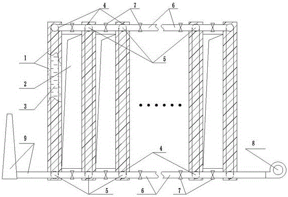
[0024] An energy-saving method for connecting graphitization furnaces in series. The method uses air as a carrier to blow the heat in the graphitization furnace pit after the graphitization process has been completed through a blower into the air passage connected by the hollow partition wall and the bottom plate. After the air flow passes through the tortuous air passage, it will be heated, taking away a large amount of heat energy, so that the material after the graphitization process has been cooled and cooled. After being heated, the air carrying a large amount of heat energy is sent to another group of new equipment through the pipe In the air passage connecting the furnace pit partition wall and the bottom plate where the material needs to be graphitized, the heat carried by the air will preheat the low temperature material to be heated through the hollow partition wall and the bottom plate, reducing the power consumption required for the low temperature material to be heated.
[0025] Further, the method realizes process control through an automatic control system. In the actual application process, for the matching of high-temperature and low-temperature furnace pits, the connecting gas passages formed by the corresponding air passages and connecting pipes between each group of graphitization furnaces are selected by selecting the valves and connecting pipes at the air inlet and outlet of each furnace pit The valve opens or closes accordingly to control the realization. The blower air volume adjustment, heat exchange temperature and time control can be detected by conventional temperature, pressure and flow meters. The entire control process can be adjusted and controlled by the DCS or PLC control system, so as to realize fully automatic switching, adjustment, monitoring and control. data record.
[0026] Such as figure 1 As shown, a device for the energy-saving method of a graphitization furnace connected in series includes a graphitization furnace body, and also includes a furnace pit partition wall 1, a bottom plate 2, an air passage 3, an air inlet and an outlet 4, a high temperature resistant stop valve 5, and a high temperature resistant pipe 6. High temperature resistant connecting valve 7, blower 8. The furnace pit partition wall 1 and the bottom plate 2 are at least two or more groups, and the furnace pit partition wall 1 and the bottom plate 2 are designed to be hollow structures, and multiple groups are hollow structures The furnace pit partition wall 1 and the bottom plate 2 of the furnace pit form a tortuous and through air passage 3, an external air inlet and outlet 4 are provided at both ends of the furnace body of the graphitization furnace body, and a high temperature resistant stop valve 5 is arranged at the air inlet and outlet 4, The gas inlet and outlet 4 of the furnace pit of all graphitization furnaces are connected by a high temperature resistant pipe 6. A high temperature resistant connecting valve 7 is arranged on the high temperature resistant pipe 6, and the high temperature resistant pipe 6 forms a tortuous path with multiple sets of through air passages 3 The connecting gas path is equipped with a large air volume blower 8 at the high temperature resistant pipe 6 at one end of the connecting gas path, and an external exhaust pipe 9 at the other end, which can be connected to a waste heat utilization system or an exhaust chimney.
[0027] Further, the furnace pit partition wall 1 and the bottom plate 2 are made of high-temperature heat-storing and thermally conductive materials.
[0028] In the actual application process, the specifications of the partition wall and the bottom plate 2 of the furnace pit can be designed from the volume of the furnace pit according to the actual production capacity. The tortuous structure of the air passage is determined by calculating the optimal heat exchange efficiency, and the pipe size and valve model are determined. For selecting the air volume and pressure of the blower, as well as the parameters of other components, it is also selected by the actual furnace pit volume.
[0029] First, connect the high temperature resistant pipeline 6 with the high temperature resistant connecting valve 7 and the high temperature resistant stop valve 5 at the air inlet and outlet 4, and the high temperature resistant stop valve 5 at the air inlet and outlet 4 is sealed with the air inlet and outlet 4 of each furnace pit partition wall 1. Connected, a blower 8 is installed at one end of the high-temperature resistant pipe 6, and an external discharge pipe 9 is connected at the other end. In this way, starting from the blower 8, the high-temperature resistant pipes 6 at both ends of the furnace pit, the air inlet and outlet 4, the multiple groups of hollow-shaped furnace pit partition walls 1 and the bottom plate 2 form a tortuous air passage 3, the high-temperature resistant pipe 6 and multiple groups The air passage 3 forms a tortuous connecting air passage, and finally can be directly connected to the outer drain tube 9 from the connecting air passage. The control method is to control by selecting the high temperature resistant stop valve 5 and the high temperature resistant connecting valve 7 at the air inlet and outlet 4 of each furnace pit to open or close accordingly, so as to realize the penetration of the corresponding furnace pit partition wall between each group of graphitization furnaces 1 and bottom plate 2 air flow channel.
[0030] In the specific implementation process, when cooling and preheating are required, first open the high temperature resistant stop valve 5 at the air inlet and outlet 4 of the high temperature furnace pit and the preheating furnace pit, and the high temperature resistant pipeline between the two furnace pits The high temperature resistant connecting valve 7 in 6 is also opened, and the valves of other furnace pits are closed. The air flow is generated by the blower 8, and the air enters the air passage 3 of the high temperature furnace pit from the air inlet at one end of the high temperature furnace pit, and transfers the heat conduction of the high temperature materials to the air flow through the furnace pit partition wall 1 and the bottom plate 2. Under the action of the blower 8, the high-temperature air flow enters the high-temperature resistant pipe 6 from the air outlet at the other end of the high-temperature furnace pit, and enters the preheating through the pipe connection valve 7 and the air inlet of the preheating furnace pit. Inside the gas passage 3 of the furnace pit. The heat of the high-temperature air stream is transferred to the preheated material through the furnace pit partition wall 1 and the bottom plate 2, and the cooled high-temperature air stream enters the high-temperature resistant pipe 6 and is finally discharged through the outer row pipe 9. In order to improve the heat utilization rate, in addition to connecting the two furnace pits that are undergoing heat exchange, all the corresponding valves of the other furnace pits are closed so that hot air will not pass through other furnace pits to ensure the highest heat exchange utilization rate.
[0031] In the actual application process, after calculating the heat balance, the material above 3000℃ can heat the air flow to above 1400℃ on average in the first day, and the hot air of 1400℃ can carry out another room temperature material in a new furnace. During preheating, the temperature can reach above 500°C. According to the statistical data in the actual production process, if the material in a furnace pit starts to be energized from the normal temperature state, when it is heated to 500°C, the power consumption is more than 20000kWh. After adopting the method and device of the present invention, while the heat energy is recovered and utilized, the cooling of high-temperature materials is also accelerated. Conventional natural cooling requires at least 7 days, and the cooling can be completed within 5 days after applying the present invention. . After the air stream has heated the preheating furnace pit, the exhaust gas temperature is still as high as about 400-500°C, and it can also be collected through the external pipe and sent to the factory waste heat utilization system for secondary heat exchange and energy saving applications. This can further improve the waste heat utilization rate and reduce the production cost of the enterprise.
[0032] In the specific implementation and application process, for the matching of high temperature and low temperature furnace pits, the connected gas path formed by the corresponding air passages and connecting pipes between each group of graphitization furnaces is achieved by selecting the valves and connections at the inlet and outlet of each furnace pit. The pipeline valve opens or closes accordingly to control the realization. The blower air volume adjustment, heat exchange temperature and time control can be detected by conventional temperature, pressure and flow meters. The entire control process can be adjusted and controlled by DCS or PLC control systems, so as to realize fully automatic switching, adjustment, monitoring and control. data record.
[0033] Using the energy-saving method and device of the tandem graphitization furnace of the present invention, using air as a carrier, the heat after the graphitization process is blown into the air duct through a blower, and the air will be heated after passing through the air duct and taken away A large amount of heat energy, so as to cool down the material after the graphitization process is completed, the heated air carrying a large amount of heat energy is sent into the furnace pit air channel where the new material needs to be graphitized, and the low temperature material that needs to be heated is preheated to reduce the low temperature material The power consumption required for heating up. The device through the energy-saving method satisfies the need to reuse waste heat energy in the process, speed up the cooling rate of high-temperature materials, thereby reducing the number of furnace pits configured for construction, and can quickly increase the initial temperature of new materials. It has a simple structure, saves heating power consumption, has a small footprint, and saves equipment and civil construction investment. Compared with the prior art, it realizes the cooling of high-temperature materials of the graphitization furnace connected in series and the secondary utilization of heat, which saves energy and improves production efficiency. The invention can be widely used in various specifications of serial graphitization furnace systems.