A fiber white-light interference demodulator using two parallel reflection planes
A parallel reflective surface and white light interference technology, which is applied in the direction of transmitting sensing components, instruments, and converting sensor output with optical devices, can solve the problems of limited application, complex structure, and high price
- Summary
- Abstract
- Description
- Claims
- Application Information
AI Technical Summary
Problems solved by technology
Method used
Image

Examples
specific Embodiment 1
[0023] Specific embodiment 1: Optical fiber F-P temperature / pressure sensing system
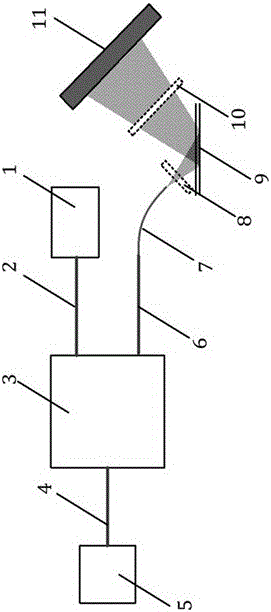
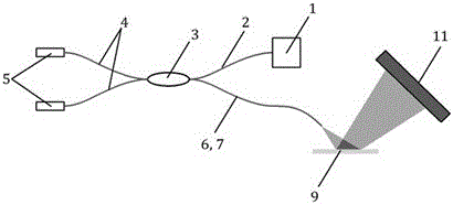
[0024] The system schematic diagram of this embodiment is attached image 3 . The entire system uses an all-fiber design. The broadband light source 1 used is a near-infrared SLED, and the optical coupler 3 is a 2×2 fiber optic coupler. The two sensors 5, the broadband light source 1 and the demodulator are incident on the optical fiber coupler. Fiber 7 connection. The measured interference sensors 5 are two F-P structure low-coherence optical fiber sensors, which are optical fiber F-P temperature sensors and optical fiber F-P pressure sensors. The optical path difference of the F-P sensor is respectively finely adjusted to ensure that the interference fringes within the dynamic range are all irradiated on the array detector 11 without overlapping. No lens is used in this system, the parallel optical reflective surfaces 9 are two surfaces of a transparent parallel quartz glass plate, and t...
specific Embodiment 2
[0026] Specific embodiment 2: Michelson displacement measurement system
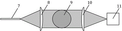
[0027] The system schematic diagram of this embodiment is attached Figure 4 . The system uses a hybrid design of free space and fiber optics. The Michelson interferometer part is a free space light path, and the demodulator part is a fiber optic light path. Broad-spectrum light source 1 uses near-infrared LEDs. A cylindrical convex lens (as the incident lens 8) is placed between the incident optical fiber 4 and the parallel optical reflection surface 9, such as figure 2As shown, the cylindrical convex lens is placed perpendicular to the incident light, and the cylindrical centerline of the cylindrical lens is in the incident plane (the incident plane refers to the plane formed by the incident beam centerline and the normal line of the reflecting surface), and its focal point is located in the incident optical fiber 4 The end face of the exit end, in order to achieve the collimation of the exit beam ...
PUM
 Abstract
Description
Claims
Application Information
 - R&D
- Intellectual Property
- Life Sciences
- Materials
- Tech Scout
- Unparalleled Data Quality
- Higher Quality Content
- 60% Fewer Hallucinations
Browse by: Latest US Patents, China's latest patents, Technical Efficacy Thesaurus, Application Domain, Technology Topic, Popular Technical Reports.
© 2025 PatSnap. All rights reserved.Legal|Privacy policy|Modern Slavery Act Transparency Statement|Sitemap|About US| Contact US: help@patsnap.com