
A microwave receiver noise measurement device and measurement method

A microwave receiver and noise measurement technology, which is applied in the direction of noise figure or signal-to-noise ratio measurement, can solve the problems of high price, increase, and inability to meet the requirements of measuring the noise figure of high-frequency receivers, etc., to achieve portability, The test process is simple, and the results show intuitive effects

Inactive Publication Date: 2018-08-14
NAT SPACE SCI CENT CAS
View PDF3 Cites 0 Cited by
  • Summary
  • Abstract
  • Description
  • Claims
  • Application Information

AI Technical Summary

Problems solved by technology

Although the noise figure analyzer is the most direct method to measure the noise figure, the disadvantages of this method are: 1) The frequency of the receiver measured by the noise figure analyzer is limited by the frequency of the known noise source. Diodes, the frequency is generally lower than 50GHz, and the high-frequency noise source needs to be imported from abroad and is expensive, so this method cannot meet the requirements of measuring the noise figure of high-frequency receivers; 2) The error of noise measurement through the noise figure analyzer increases with the increases rapidly with the increase of noise figure of the receiver, so this method is only suitable for receivers with lower noise figure
[0012] This method needs to predetermine the receiver gain and output power spectral density, which can be measured by a spectrum analyzer. The disadvantage of this method is that the measured noise power spectral density is limited by the noise floor of the spectrum analyzer. When the noise figure is low ( Generally less than 10dB), (PNOUTD-Gain) is close to -170dBm / Hz, when the receiver gain is 20dB, it is necessary to measure the noise power spectral density of -150dBm / Hz, which is lower than the noise floor of most spectrum analyzers

Method used


Image

  • A microwave receiver noise measurement device and measurement method
  • A microwave receiver noise measurement device and measurement method
  • A microwave receiver noise measurement device and measurement method

Examples


Embodiment Construction

[0037] The present invention will be further described now in conjunction with accompanying drawing.

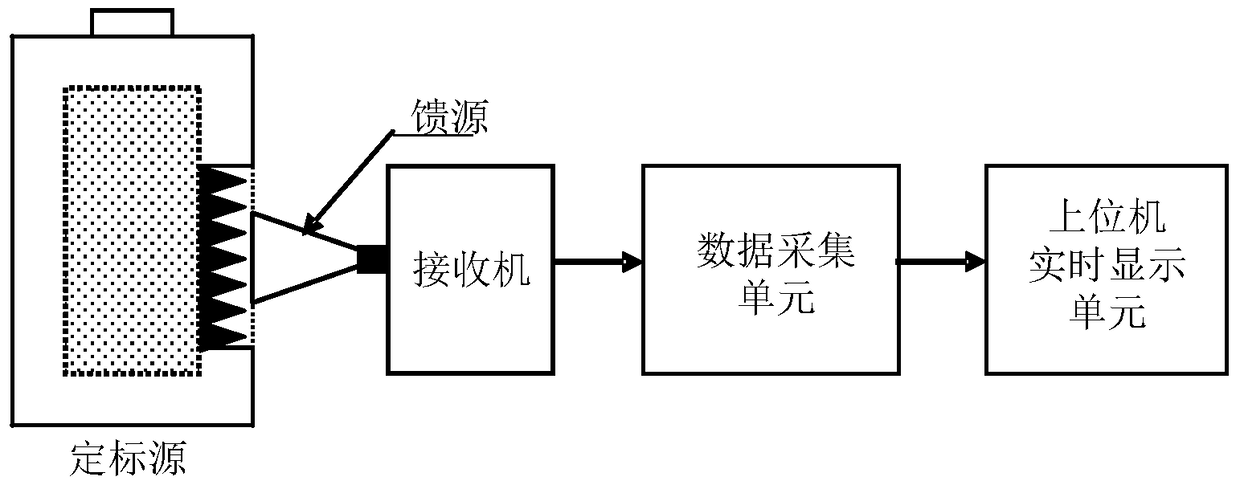
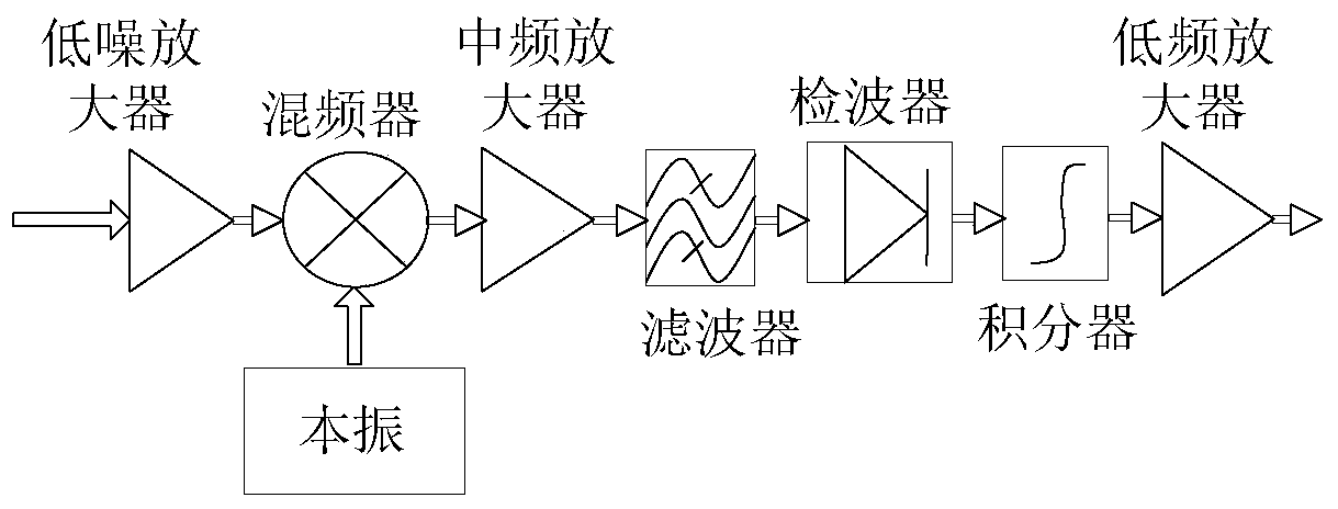
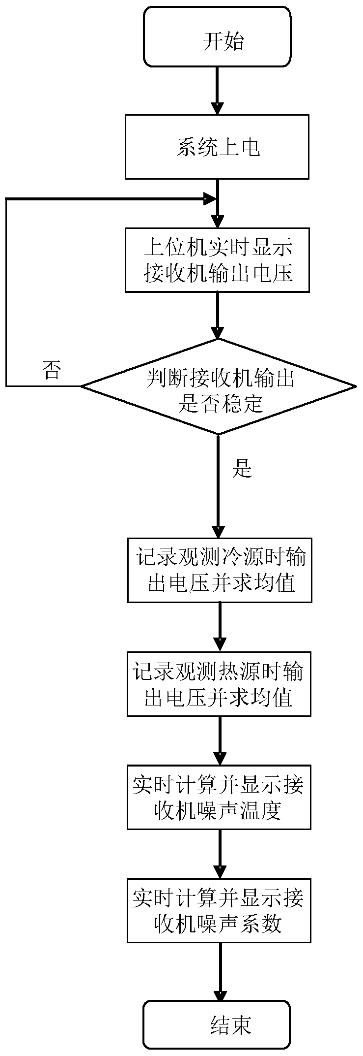
[0038] figure 1 It is a structural schematic diagram of a noise measuring device for a microwave receiver of the present invention. As shown in the figure, the noise measurement device of the present invention includes a calibration source, a feed source, a data acquisition unit, and a real-time display unit of an upper computer; wherein, the feed source is used to receive microwave radiation signals from the atmosphere and the calibration source, and then Input the microwave radiation signal into the microwave receiver to be tested; the microwave receiver to be tested sequentially performs down-conversion, amplification, filtering, wave detection, integration and low-frequency amplification processing on the microwave radiation signal, and outputs a voltage signal; the data acquisition The unit collects and stores the voltage signal output by the receiver, and transmits it ...


PUM


Abstract

The invention relates to a microwave receiver noise measuring device comprising a calibration source, a feed source, a data acquisition unit, and a principal computer real-time display unit. The feed source is used for receiving microwave radiation signals from atmosphere and the calibration source and inputting the microwave radiation signals to a microwave receiver to be measured; the microwave receiver to be measured carries out down-conversion, amplification, filtering, detection, integration and low-frequency amplification of the microwave radiation signals in sequence, and outputs voltage signals; the data acquisition unit acquires and stores the voltage signals output by the receiver, and transmits the voltage signals to the principal computer real-time display unit; and the principal computer real-time display unit processes the voltage signals according to the observed calibration source to get the receiver noise temperature and the noise coefficient of the receiver, and displays the voltage signals, the receiver noise temperature and the noise coefficient in real time.

Description

technical field [0001] The invention relates to the field of noise measurement, in particular to a microwave receiver noise measurement device and a measurement method. Background technique [0002] In the working process of the receiver, the addition of receiver noise limits the signal-to-noise ratio and sensitivity of the signal, especially the signal received by the microwave receiver is relatively weak, so its noise characteristics are particularly important and have a direct impact on system sensitivity. [0003] Receiver noise temperature and noise figure are the key indicators to measure the receiver. At present, a measurement method is to use a known noise source and a noise figure analyzer to measure. Use the noise generated by the noise source to drive the receiver under test, and measure the output of the receiver under test through the noise figure analyzer; since the noise figure analyzer knows the input noise and signal-to-noise ratio of the noise source, the n...

Claims


Application Information

Patent Timeline
Patent Type & Authority Patents(China)
IPC IPC(8): G01R29/26
Inventor 张瑜张升伟何杰颖
Owner NAT SPACE SCI CENT CAS
Learn More