High resolution radar fast imaging method based on generalized reflectivity model

A technology of radar imaging and imaging method, which is applied in the direction of radio wave reflection/re-radiation, utilization of re-radiation, instruments, etc., and can solve problems such as ghosting, high computational complexity of tomographic methods, target recognition and classification burden, etc.

Inactive Publication Date: 2016-08-10
PEKING UNIV
View PDF0 Cites 8 Cited by
  • Summary
  • Abstract
  • Description
  • Claims
  • Application Information

AI Technical Summary

Problems solved by technology

Although the imaging accuracy of the tomography method is higher than that of the migration method, the computational complexity of the tomography method is much higher than that of the migration method
[0005] From the above analysis, it can be seen that the above two solving methods have the disadvantages of large amount of calculation, and are only suitable for lower frequency bands and smaller target sizes. In the face of large-scale high-resolution imaging problems, the two methods are powerless
The current radar imaging process is limited by the above two overly simple imaging models, resulting in the existence of a large number of ghost images in the imaging results, which brings a serious burden to target recognition and classification in the post-processing process

Method used


Image

  • High resolution radar fast imaging method based on generalized reflectivity model
  • High resolution radar fast imaging method based on generalized reflectivity model
  • High resolution radar fast imaging method based on generalized reflectivity model

Examples


Embodiment 1

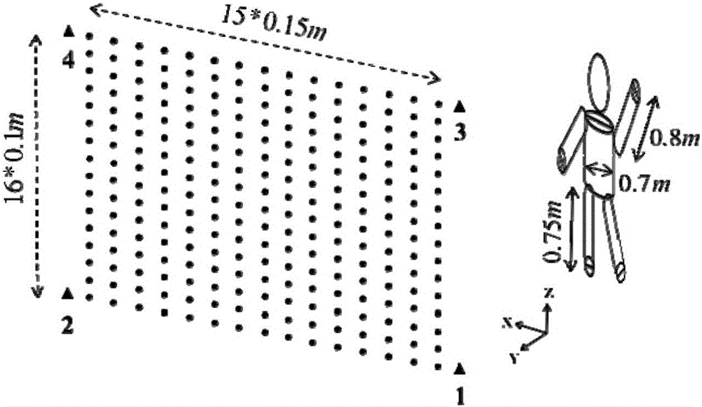
[0067] In this embodiment, the structure of the 3D simulation system is as follows figure 1 As shown, the radar imaging system adopts the multiple-input multiple-output antenna technology MIMO (Multiple-Input Multiple-Output) radar imaging system with separate transceivers.

[0068] The high-resolution radar rapid imaging method based on the generalized reflectivity model of the present embodiment comprises the following steps:

[0069] 1) Establish a radar imaging system to obtain radar scattering data:

[0070] The radar imaging system includes four transmitters 1-4, 240 receivers, the bandwidth of the transmitted signal is 1-3Ghz, the transmitter transmits the signal to the target imaging area, the receiver receives the echo signal, and the tth transmitter transmits the signal After that, the echo signal at each receiver can be expressed as y F,t =[y F,t,1 ; у F,t,2 ;… у F,t,R ]; figure 1 The four triangles in the figure represent the four transmitters 1-4; the dots o...

Embodiment 2

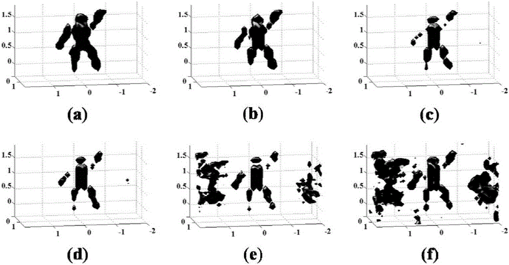
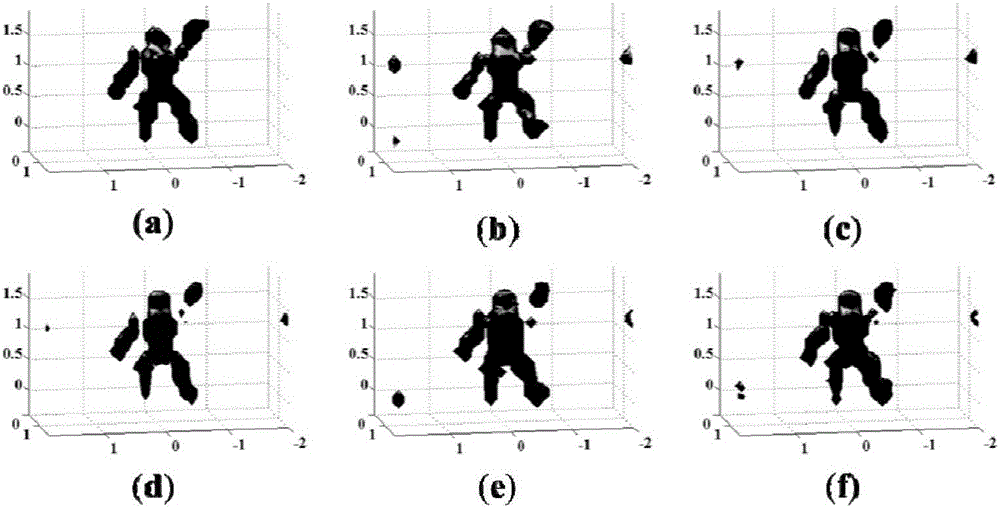
[0093] In this embodiment, according to the second sub-imaging region division method in b) of step 3), that is, the neighbor element constant method divides the target imaging region into B sub-imaging regions, and in this embodiment, the target imaging region is divided into B= 1, 4, 8, 12, 24 and 32 sub-imaging areas. Others are the same as embodiment one. The number of divided sub-imaging areas is different, and different imaging effects are obtained respectively, such as image 3 shown.

[0094] In this embodiment, the relationship between dividing different numbers of sub-imaging regions and the average imaging time is shown in Table 2 below:

[0095]

[0096]

[0097] Table 2

[0098] As can be seen from Table 2, Embodiment 2 verifies the correctness of the conclusion of Embodiment 1: as the number of sub-imaging regions increases, the average imaging time decreases exponentially, and it can be seen that the division of sub-imaging regions is greatly accelerate...


PUM


Abstract

The invention discloses a high resolution radar fast imaging method based on a generalized reflectivity model. According to the invention, the conventional radar imaging Bonn approximation model can be extended, and the anisotropic characteristic of the target and the characteristic of the target having different action effects on the signals of different frequency bands can be added to the model; the model is closer to the actual signal model, and the radar imaging effect can be enhanced, and the good foundation can be laid for realizing the high resolution radar imaging; by using three sparse characteristics of the target generalized reflectivity, the radar imaging system can be divided into the sub-apertures or sub-frequency bands for the approximation calculation; according to the system function characteristics, the imaging area can be divided into a series of sub-imaging areas, and then the imaging speed can be greatly accelerated; by adopting the dual transformation, the conventional radar imaging problem can be changed into the image processing problem based on the physical mechanism. The radar imaging precision can be guaranteed, and the radar imaging speed can be accelerated, and therefore the technical problem of the inability of realizing the large-scale high-resolution radar real-time imaging can be effectively solved.

Description

technical field [0001] The invention relates to radar imaging technology, in particular to a high-resolution radar fast imaging method based on a generalized reflectivity model. Background technique [0002] With the rapid development of economy and society, radar imaging systems have been widely used in geographic science, medicine and various other military and civilian scenarios. Since the radar imaging system uses high-frequency electromagnetic waves, it has a strong non-metal penetration ability and can effectively detect hidden targets. For example: at night, remote sensing imaging of the enemy's military base can provide timely insight into the enemy's military operations; in the process of anti-terrorist operations and hostage rescue, high-resolution imaging of non-cooperative targets behind the wall can provide powerful information for formulating rescue methods. Reference: In public places such as airports and railway stations, quickly and harmlessly conduct secur...

Claims


Application Information

Patent Timeline
Patent Type & Authority Applications(China)
IPC IPC(8): G01S13/89
CPCG01S13/89
Inventor 王龙刚李廉林
Owner PEKING UNIV
Why Eureka
Try Eureka