Dual polarized one-dimensional tightly coupled ultra wide band and wide angle sweep phased array antenna

A wide-angle scanning, strong coupling technology, applied in the field of antennas, can solve the problems of increasing the weight of the antenna, high requirements for the coupling strength between units, and high density, and achieves widening the low frequency impedance bandwidth, lightweight design, and improving low frequency reactance. Effect

Active Publication Date: 2016-08-10
UNIV OF ELECTRONICS SCI & TECH OF CHINA
View PDF3 Cites 28 Cited by
  • Summary
  • Abstract
  • Description
  • Claims
  • Application Information

AI Technical Summary

Problems solved by technology

[0004] However, this new type of phased array technology currently has some shortcomings: (1) Due to the high requirements for the coupling strength between elements, this tec

Method used


Image

  • Dual polarized one-dimensional tightly coupled ultra wide band and wide angle sweep phased array antenna
  • Dual polarized one-dimensional tightly coupled ultra wide band and wide angle sweep phased array antenna
  • Dual polarized one-dimensional tightly coupled ultra wide band and wide angle sweep phased array antenna

Examples


Embodiment 1

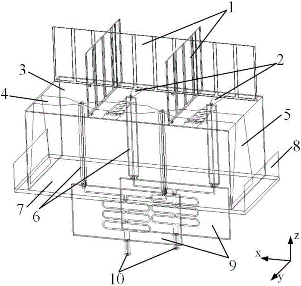
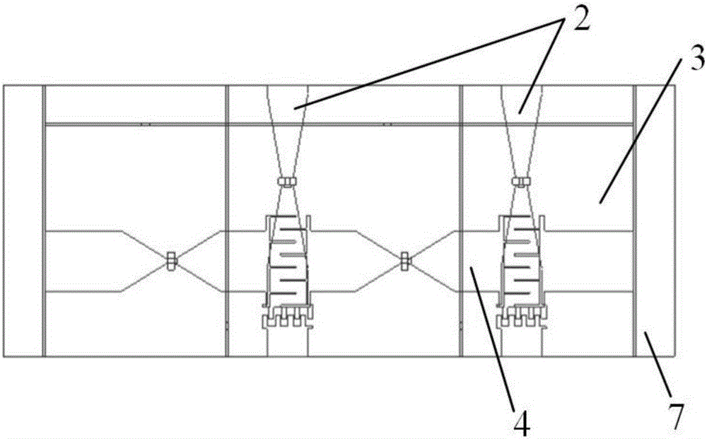
[0018] refer to figure 2 In the unit structure shown, a one-dimensional periodic boundary condition is used to simulate the simulation of the array element of the present invention in a one-dimensional infinite array environment. The unit consists of upper and lower layers of orthogonal interdigitated dipoles 2 and 4, and a printed patch part 5 that extends vertically and gradually; 3 is a thickness of 0.508mm and a relative permittivity r = 2.2 TLY-5 dielectric layer, 2 and 4 are printed on the upper and lower surfaces of the microwave dielectric layer respectively; above 3 there is a parasitic dielectric layer 1 placed orthogonally, the material and thickness of the dielectric layer are the same as 3, double-sided printed metal ; 6 is the feeding structure of the gradient microstrip line, and the front and back sides are respectively coated with a gradient metal strip and a long metal strip; 7 is the reflective floor; 8 is the metal fence on both sides of the floor; The po...

Embodiment 2

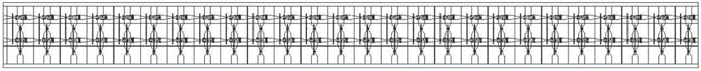
[0019] Embodiment 2: In this embodiment, 26 structures in Embodiment 1 are arranged one-dimensionally, and one unit on each side is connected to a 50-ohm matching load as a dummy. Its schematic diagram is as follows figure 1 shown.

[0020] Considering the conditions of existing simulation hardware facilities, this embodiment adopts the pattern superposition principle in electromagnetic simulation to simulate the pattern of the line array. The radiation pattern is shown in Figure 7. It can be seen from the array pattern that the linear array has a main beam at each scanning angle, pointing to the scanning direction accurately. The sidelobe and cross-polarization levels of the antenna are basically kept above -15dB.


PUM

PropertyMeasurementUnit
Thicknessaaaaaaaaaa

Abstract

The invention discloses a dual polarized one-dimensional tightly coupled ultra wide band and wide angle sweep phased array antenna, which comprises two columns of horizontal polarization and 26 rows of vertical polarization interdigital coupled dipole antennas. The basic structure of the phased array antenna comprises upright parasitic printing medium plates for wide angle scanning, upper layer horizontal polarization interdigital dipoles, medium plates, lower layer vertical polarization interdigital dipoles as well as their horizontally extending parts, vertical polarization dipoles as well as their uprightly gradual changing and extending parts, the gradual changing microstrip line feed structures for performing feed at the ports of the dipoles, reflection grounding plates, metal enclosures at two sides of the grounding plates, power dividers and 50-ohm coaxial adapters. The tightly coupling structures among the units help the antenna achieve an ultra wide band effect. A wide angle scanning function can be achieved because parasitic printing medium plates are introduced to take the place of conventional and heavy wide angle resistance matching layers with the consequence of reduced weight and size.

Description

technical field [0001] The invention belongs to the technical field of antennas, and relates to a dual-polarization ultra-wideband phased array antenna, in particular to a dual-polarization ultra-wideband angular scanning one-dimensional phased array antenna for modern communication systems and radar systems. Background technique [0002] The phased array antenna with broadband and wide-angle scanning characteristics is a commonly used antenna form in modern radar and electronic warfare systems. With the rapid development of modern military electronic technology, the performance requirements of various military electronic systems for the wide bandwidth and wide scanning angle of the phased array continue to increase. The traditional broadband phased array design is to first design a single isolated unit with a wider bandwidth than the phased array, and then organize the designed broadband antenna units into an array. When forming an array, it is desirable to increase the di...

Claims


Application Information

Patent Timeline
IPC IPC(8): H01Q3/34H01Q21/06H01Q1/50
CPCH01Q1/50H01Q3/34H01Q21/06
Inventor 杨仕文张航宇陈益凯聂在平屈世伟
Owner UNIV OF ELECTRONICS SCI & TECH OF CHINA
Why Eureka
Try Eureka