
Display rack for shades of nail varnish

A beauty device and skin technology, applied in the field of beauty devices, can solve the problems of feeling heat, skin heat, etc., and achieve the effects of improving the degree of freedom, improving the heat dissipation efficiency, and improving the appearance design.

Inactive Publication Date: 2016-08-10
YA MAN LTD
View PDF13 Cites 8 Cited by
  • Summary
  • Abstract
  • Description
  • Claims
  • Application Information

AI Technical Summary

Problems solved by technology

[0006] In the above-mentioned light irradiation type hair removal device, the hair is removed by applying heat energy to the skin surface, especially the hair root part, so there is a problem that the skin will heat up during use, and it will feel hot when it is continuously used.

Method used


Image

  • Display rack for shades of nail varnish
  • Display rack for shades of nail varnish
  • Display rack for shades of nail varnish

Examples


Embodiment 2

[0073] As a second embodiment of the present invention, it is also possible to provide a light irradiation type hair removal device having two open-close rollers on both sides of the light-emitting part, wherein the open-close rollers have at least a cooling function.

[0074] That is, if Figure 5 As shown, in the lower part of the epilator main body (200), two open-close roller bodies (202) (202) are arranged on the left and right sides of the light emitting part (203). In this embodiment, the treatment target part of the skin surface is located below the epilator main body (200), and the flash light is irradiated downward toward the treatment target part from the irradiation window part of the light emitting part (203).

[0075] 2 open-close rollers (201) (202) are supported by the open-close mechanism (204), such as Figure 5 As shown in (a) and (b), open and close to the left and right. The opening and closing mechanism (204) is applied force towards the center, under t...

no. 3 example

[0086] Figure 7 An epilator body (300) of a third embodiment of the present invention is shown. Two razors (301) (302) are provided on the left and right sides of the light emitting part (303) on the surface facing the treatment target part of the epilator main body (300). The two razors consist of a fine-gauge fine-gauge razor (301) for fine shaving and a coarse-gauge coarse-gauge razor (302) for rough shaving.

[0087] According to the above structure, in the state of (a), the shaver is slid on the skin surface toward the hair of the treatment target part, and in the state of (b), the hair is first removed by the thick shaver (302). hair. Coarse razors can be pre-conditioned to a length suitable for flash epilation using the light emitting part (303). Furthermore, in the state of (c), the light-emitting part (303) emits flash light to apply heat to the root of the hair to perform hair removal treatment.

[0088] After the flash hair removal, as shown in the state of (d)...


PUM


Abstract

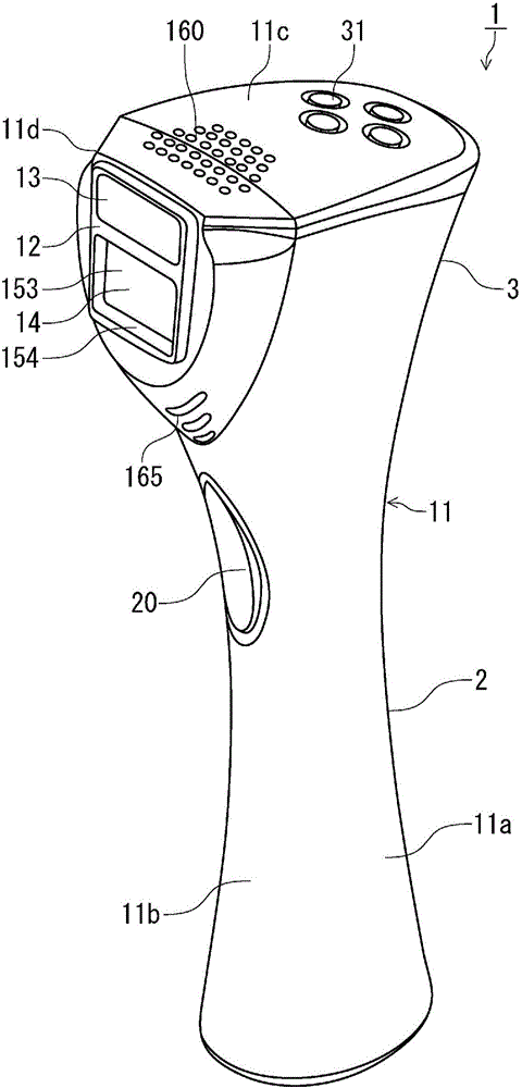
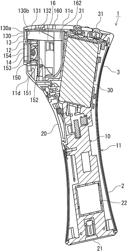
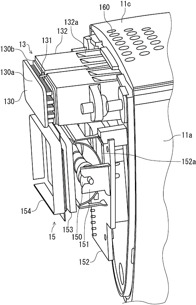
[Problem] To provide, in a cosmetic device furnished with a light-irradiating depilatory mechanism configured such that the cosmetic device is equipped with a cooling means for cooling the skin surface, a technology for continuously performing cooling and light irradiation during use and efficiently cooling the cooling means and the light-emitting unit. [Solution] Provided is a cosmetic device (1) furnished with a light-irradiating depilatory mechanism for performing hair removal treatment on a skin surface by irradiating light from a light-emitting unit (15) on the skin surface, the cosmetic device: having a grip section (2) that the user grasps and a skin guiding surface (12) to be brought into contact with the area to be treated while the device is grasped; and, in a configuration in which the irradiation window (14) through which light from the light-emitting unit (13) is irradiated and the cooling means (13) for cooling the skin surface are disposed on the same surface on said skin guiding surface (12), being provided with a fan (16) for simultaneously generating an air stream for heat dissipation from the cooling means (13) and an air stream for air-cooling the light-emitting unit (15).

Description

technical field [0001] The present invention relates to a beauty device equipped with a light irradiation type hair removal mechanism, and particularly relates to cooling and heat radiation technology of the beauty device. Background technique [0002] Conventionally, there is a light irradiation type hair removal device that includes a light irradiation unit that irradiates light onto the skin surface to perform hair removal or shaving. For example, Patent Document 1 (Japanese Unexamined Patent Publication No. 2002-360336) of the present applicant arranges a plurality of semiconductors for irradiating laser light on both sides of a rotating disk of an electric hair puller or a hair-plucking actuator of a clamping claw. In the structure of the laser diode, the semiconductor laser diode is inserted into the heat sink through the through hole, and a spherical lens is arranged in front of its light-emitting surface. The spherical lens condenses the laser light of the semicondu...

Claims


Application Information

Patent Timeline
Patent Type & Authority Applications(China)
IPC IPC(8): A45D26/00A61N5/067B26B19/10
CPCA45D26/00A45D26/0061A45D2200/205A61B18/203A61B2018/00047A61B2018/00476
Inventor 山崎岩男
Owner YA MAN LTD
Learn More