
Calcium carbide sensible heat recovery device

A technology of sensible heat recovery and calcium carbide, which is applied to heat exchangers, heat exchanger types, indirect heat exchangers, etc., can solve the problems of unusable heat energy, consumption of manpower and materials, and high labor intensity, so as to achieve the goal of avoiding crushing process, saving manpower and material resources

Inactive Publication Date: 2016-08-17
SHANGHAI TAIXU ENERGY SAVING SCI & TECHCO
View PDF5 Cites 6 Cited by
  • Summary
  • Abstract
  • Description
  • Claims
  • Application Information

AI Technical Summary

Problems solved by technology

[0003] The deficiency that exists in this prior art is: calcium carbide furnace flows into the molten state calcium carbide temperature of forming mold more than 1600 degree, in natural cooling process, will release a large amount of heat energy (comprising sensible heat and phase transformation heat), calculate this part Heat energy, the production of calcium carbide per ton is about 700kWh, equivalent to 224kg of standard coal, and the heat loss is relatively large, accounting for more than 24% of the power consumption of calcium carbide. This part of heat energy cannot be used, that is, sensible heat cannot be recovered
[0006] Although in this invention, the sensible heat can be recovered simply, but after the calcium carbide is solidified, it is necessary to use a jaw crusher to crush the calcium carbide. Each weight of calcium carbide is nearly one ton, and the crushing work alone is not only labor-intensive, but also dusty environment. Pollution, severe damage to crushing machinery and equipment, consumes a lot of manpower and materials

Method used


Image

  • Calcium carbide sensible heat recovery device
  • Calcium carbide sensible heat recovery device
  • Calcium carbide sensible heat recovery device

Examples


Embodiment Construction

[0029] In the following, the present invention will be specifically described through exemplary embodiments. It should be understood, however, that elements, structures and characteristics of one embodiment may be beneficially incorporated in other embodiments without further recitation.

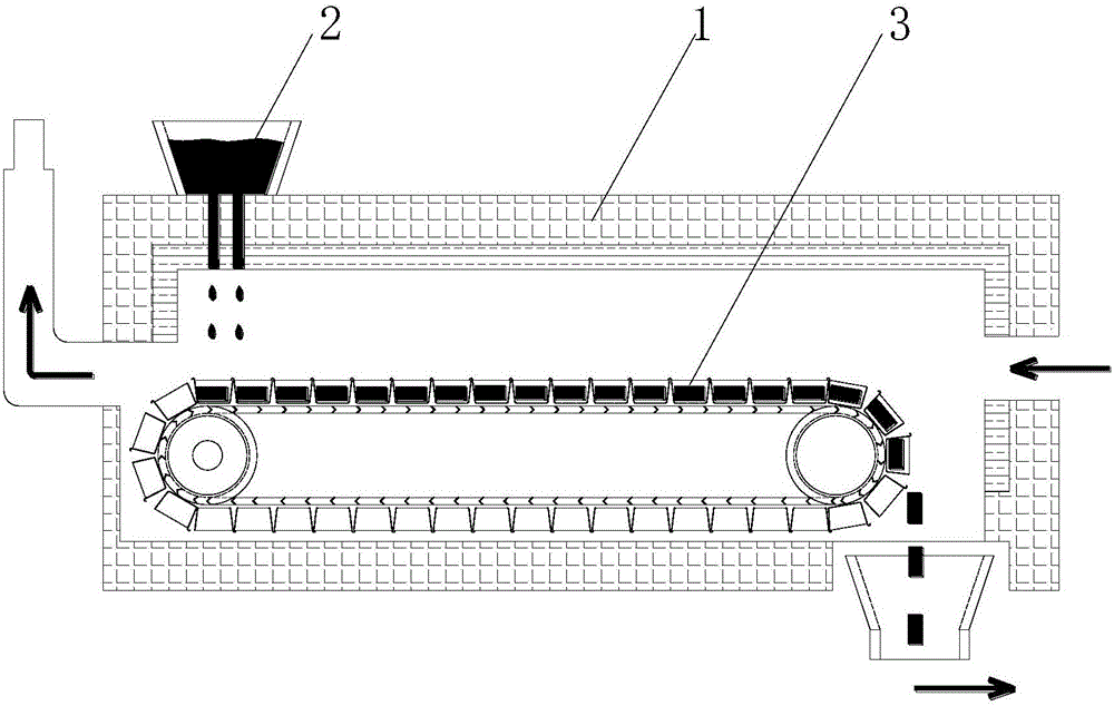
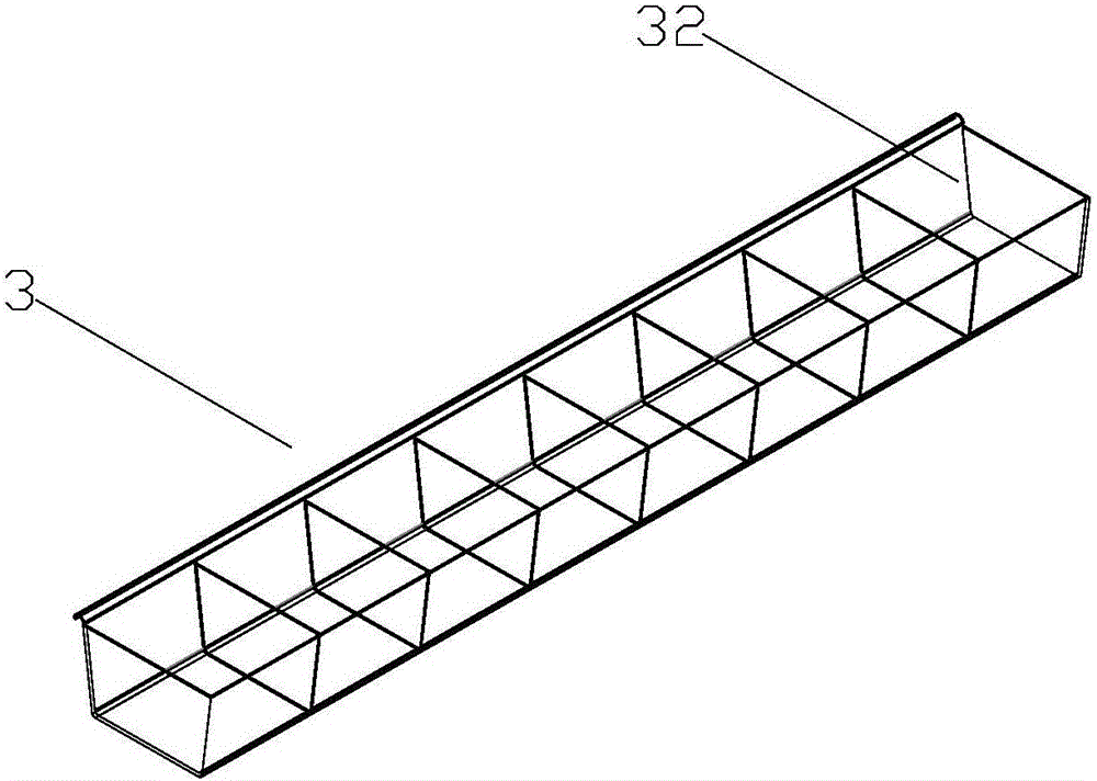
[0030] see figure 1 as well as figure 2 , is a schematic diagram of the calcium carbide sensible heat recovery device in the present invention. Such as figure 1 , figure 2 As shown, the calcium carbide sensible heat recovery device includes a heat exchange furnace 1, a recyclable forming mold 3 is arranged in the chamber of the heat exchange furnace 1, the forming mold 3 has a feeding end and a discharging end, and the feeding end of the forming mold 3 A plurality of air cooling devices 4 are arranged on the upper part between the outlet end and the molten calcium carbide in the forming mold to cool the calcium carbide into solid calcium carbide; the side wall of the heat exchange furn...


PUM


Abstract

The invention provides a calcium carbide sensible heat recovery device. The device comprises a recuperative furnace, wherein a forming mold capable of carrying out cycle operation is arranged in a chamber of the recuperative furnace and is provided with a feed end and a discharge end; a plurality of air cooling devices are arranged above the part between the feed end and discharge end of the forming mold to cool calcium carbide in a molten state at the feed end in the forming mold to form solid calcium carbide at the discharge end; and a hot air recovery channel is arranged on the side wall of the recuperative furnace to recover the heat generated when calcium carbide on the forming mold is converted from the molten state to a solid state. The calcium carbide sensible heat recovery and non-crushing device has the advantages that by arranging the forming mold capable of carrying out cycle operation inside the recuperative furnace, calcium carbide is converted from the molten state to the solid state via the effects of the air cooling devices at the top of the recuperative furnace in the process of conveying calcium carbide by the forming mold, and the heat generated in the conversion process is recovered and utilized by the hot air recovery channel of the recuperative furnace, thus achieving recovery of the calcium carbide sensible heat.

Description

technical field [0001] The invention relates to a heat energy recovery and breakage-free device in calcium carbide production, in particular to a calcium carbide sensible heat recovery device for converting molten calcium carbide into a solid with a certain shape. Background technique [0002] The production process of the existing calcium carbide production enterprises is as follows: the molten calcium carbide discharged from the heat exchange furnace flows into the high temperature resistant calcium carbide crucible, the molten calcium carbide is pulled to a certain place in the calcium carbide crucible for natural cooling, and after the calcium carbide is solidified, The calcium carbide is hoisted out with a bridge crane, placed on the cast iron floor to cool, and after cooling to a moderate level, the calcium carbide is crushed to a qualified particle size, then packed in grades, and sent to the finished product warehouse. [0003] The deficiency that exists in this prio...

Claims


Application Information

Patent Timeline
IPC IPC(8): C01B31/32F28D21/00
CPCF28D21/0012Y02P20/10
Inventor 戴如宏
Owner SHANGHAI TAIXU ENERGY SAVING SCI & TECHCO
Learn More