Method and device for drying sludge by utilizing thermal power plant waste heat

A technology for sludge drying and thermal power plants, applied in separation methods, chemical instruments and methods, water/sludge/sewage treatment, etc., which can solve problems such as unfavorable sludge transportation, storage and further treatment, high-grade electric energy, energy waste, etc. , to achieve the effects of easy large-scale scale, energy saving, and high space utilization

Inactive Publication Date: 2016-08-17
SOUTH CHINA UNIV OF TECH
View PDF7 Cites 15 Cited by
  • Summary
  • Abstract
  • Description
  • Claims
  • Application Information

AI Technical Summary

Problems solved by technology

[0003] Even after conventional mechanical dehydration of municipal sludge, its water content is still above 80%, which is extremely unfavorable for sludge transportation, storage and further tr

Method used


Image

  • Method and device for drying sludge by utilizing thermal power plant waste heat
  • Method and device for drying sludge by utilizing thermal power plant waste heat

Examples


Embodiment

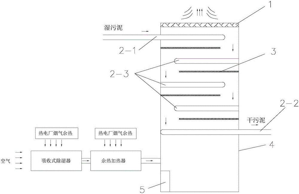
[0035] As shown in Figures 1 and 2. The invention discloses a sludge drying device combined with waste heat utilization of a thermal power plant, comprising a furnace 4, a plate-type feeding conveyor belt 2-1 arranged on the inner upper part of the furnace 4, and a plate-type discharge conveying belt 2-2 arranged on the inner lower part of the furnace 4 ;

[0036] Between the plate feed conveyer belt 2-1 and the plate discharge conveyer belt 2-2, there are multi-layer middle plate conveyer belts 2-3 staggeredly distributed from top to bottom; The internal airflow channels are spaced into S-shaped airflow channels;

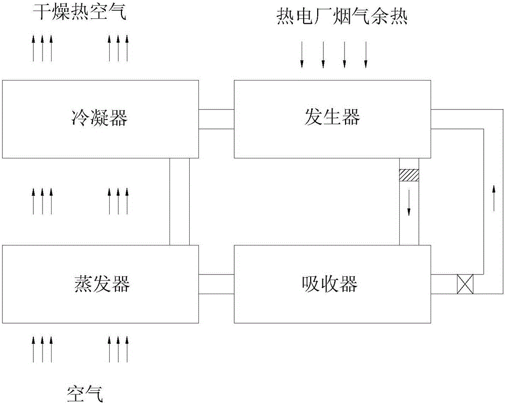
[0037] The lower side wall of the furnace 4 is provided with a drying air supply device; the drying air passes through the plate type discharge conveyor belt 2-2, the middle layer plate type conveyor belt 2-3 and the plate type feed conveyor belt 2-1 sequentially from bottom to top, drying Under the action of their diversion, the wind circulates in the furnace 4 ...


PUM


Abstract

The invention discloses a sludge drying method combined with waste heat utilization in a thermal power plant and a device thereof, comprising a plate-type feeding conveyer belt and a plate-type discharge conveying belt in which a furnace is arranged in the furnace; From top to bottom, there are multiple layers of middle-layer plate conveyor belts; each layer of middle-layer plate conveyor belts divides the internal airflow channel of the furnace into an S-shaped airflow channel; the drying wind presents an S-shaped flow trajectory in the furnace under the action of their diversion. Circuitous flow; the sludge rolls down from the end of the plate feed conveyor belt to the plate type middle layer conveyor belt of the first layer, and then rolls down from the end of the first layer plate type middle layer conveyor belt to the plate type discharge conveyor belt in turn, so that the sludge It moves in the furnace in an S-shaped trajectory from top to bottom, and is finally sent out by the plate-type discharge conveyor belt. The device can save a large amount of high-grade electric energy, and realize drying with low-grade flue gas waste heat, high efficiency, energy saving, environmental protection, high space utilization rate, and easy large-scale scale.

Description

technical field [0001] The invention relates to a sludge drying process, in particular to a sludge drying method combined with thermal power plant waste heat utilization and a device thereof. Background technique [0002] With the development of cities, the number and scale of urban sewage treatment plants have grown rapidly, and these sewage treatment plants have produced a large amount of sludge. How to properly dispose of sludge and realize sludge recycling has become a key area of ​​scientific research. [0003] Even after conventional mechanical dehydration, the water content of municipal sludge is still above 80%, which is extremely unfavorable for sludge transportation, storage and further treatment. At present, the most common sludge drying method is blast drying by electric heating. However, this drying method consumes a large amount of high-grade electric energy, resulting in energy waste. Contents of the invention [0004] The object of the present invention is...

Claims


Application Information

Patent Timeline
IPC IPC(8): C02F11/12B01D53/86B01D46/00
CPCC02F11/12B01D46/00B01D53/86C02F2303/06
Inventor 廖艳芬林延余昭胜方诗雯林有胜范云龙马晓茜
Owner SOUTH CHINA UNIV OF TECH
Why Eureka
Try Eureka