
Test apparatus and method for evaluating erosion corrosion of oil and gas pipelines at high flow rates

A technology for scouring corrosion and oil and gas pipelines, applied in the field of oil and gas pipeline corrosion evaluation, can solve problems such as unsuitable for laboratory research, inconvenient operation, and high system operating costs

Active Publication Date: 2018-10-16
BC P INC CHINA NAT PETROLEUM CORP +1
View PDF4 Cites 7 Cited by
  • Summary
  • Abstract
  • Description
  • Claims
  • Application Information

AI Technical Summary

Problems solved by technology

[0003] During the process of transporting natural gas in the pipeline of the ground gathering and transportation system of the high-pressure gas field, the produced water along with the high-velocity natural gas causes erosion and corrosion at the bottom of the pipeline. At present, the most ideal way to simulate the erosion and corrosion of oil pipelines is to install a full-scale pipe section skid on the oil and gas field site Install experimental devices, but on-site experiments are not only costly, but also inconvenient to operate, and many research instruments and equipment cannot be used in the field for a long time
Therefore, the researchers designed a rotary motor type (a rotary experimental device for simulating the erosion corrosion of the inner wall of the pipeline, 201020678306X; a rotary ring pipe multiphase flow erosion corrosion simulation test device, 201410017976X; a test device for axial erosion corrosion of samples and method, 2014105916156), impact jet type (a jet erosion test device, 201320661171X; device and method for simulating and measuring fluid erosion corrosion rate on pipelines with variable incident angle, 2012102644061), pipeline circulation type and other erosion test systems ( Engineering pipe erosion corrosion test device, 201420323933X), for the high-velocity gas field ground gathering and transportation pipeline system, it is obvious that the fluid flow mode of the rotating type and the impact jet type is different from the fluid flow mode of the actual gathering and transportation pipeline, and the existing pipeline Most of the circulation type is a full-scale large-scale pipeline system. Due to the large amount of test medium required during the experiment, it is very difficult to remove oxygen, and the system operation cost is very high, so it is not suitable for laboratory research.

Method used


Image

  • Test apparatus and method for evaluating erosion corrosion of oil and gas pipelines at high flow rates
  • Test apparatus and method for evaluating erosion corrosion of oil and gas pipelines at high flow rates
  • Test apparatus and method for evaluating erosion corrosion of oil and gas pipelines at high flow rates

Examples


Embodiment 1

[0045] Corrosion Behavior of Carbon Steel Pipe Lines in Oil and Gas Produced Water at High Flow Rates

[0046] Step 1, sample preparation: the carbon steel pipe section is processed into a smooth sample, the surface of the sample is polished step by step with 200#, 400#, 800# and 1200# sandpaper, and the size of the sample is measured and weighed;

[0047] Step 2, simulated solution preparation: in parts by mass, 50 parts of NaCl, 23 parts of MgSO 4 , 25 parts of CaCl 2 , 10 parts of NaHCO 3 and 2 servings of KHCO 3 Mix evenly with 10 liters of deionized water to prepare a simulated solution;

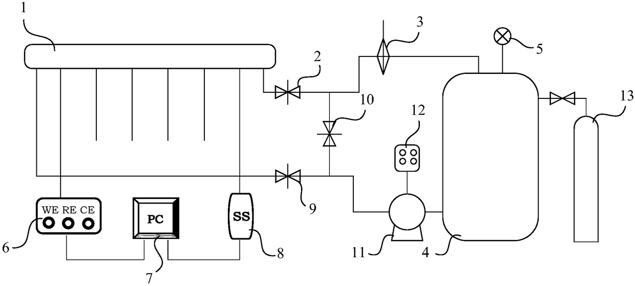
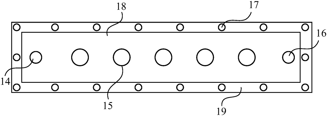
[0048] Step 3, sample installation and medium filling: install the 3 processed samples as a group of parallel samples in the sample installation port of the thin liquid layer flushing channel 1, and add the prepared salt solution to the fluid storage tank 4. , then through CO 2 The gas cylinder 13 slowly injects CO into the fluid storage tank 4 2 Gas, stop the injection when the p...

Embodiment 2

[0052] Corrosion Behavior of Carbon Steel Pipe Lines in Oil and Gas Produced Water at High Flow Rates

[0053] Step 1, sample preparation: the carbon steel pipe section is processed into a smooth sample, the surface of the sample is polished step by step with 200#, 400#, 800# and 1200# sandpaper, and the size of the sample is measured and weighed;

[0054] Step 2, preparation of simulated solution: in parts by mass, 60 parts of NaCl, 20 parts of MgSO 4 , 33 parts of CaCl 2 , 8 parts of NaHCO 3 and 3 servings of KHCO 3 Mix evenly with 10 liters of deionized water to prepare a simulated solution;

[0055] Step 3, sample installation and medium filling: install the 3 processed samples as a group of parallel samples in the sample installation port of the thin liquid layer flushing channel 1, and add the prepared salt solution to the fluid storage tank 4. , then through CO 2 The gas cylinder 13 slowly injects CO into the fluid storage tank 4 2 Gas, stop the injection when the...

Embodiment 3

[0059] Corrosion Behavior of Carbon Steel Pipe Lines in Oil and Gas Produced Water at High Flow Rates

[0060] Step 1, sample preparation: the carbon steel pipe section is processed into a smooth sample, the surface of the sample is polished step by step with 200#, 400#, 800# and 1200# sandpaper, and the size of the sample is measured and weighed;

[0061] Step 2, preparation of simulated solution: in parts by mass, 70 parts of NaCl, 18 parts of MgSO 4 , 39 parts of CaCl 2 , 7 parts of NaHCO 3 and 4 servings of KHCO 3 Mix evenly with 10 liters of deionized water to prepare a simulated solution;

[0062] Step 3, sample installation and medium filling: install the 3 processed samples as a group of parallel samples in the sample installation port of the thin liquid layer flushing channel 1, and add the prepared salt solution to the fluid storage tank 4. , then through CO 2 The gas cylinder 13 slowly injects CO into the fluid storage tank 4 2 Gas, stop the injection when the...


PUM

PropertyMeasurementUnit
thicknessaaaaaaaaaa

Abstract

The invention discloses a test device and a method for evaluating scouring corrosion of an oil-gas pipeline under a high flow rate. The test device comprises a thin liquid layer scouring channel and a fluid storage tank, wherein a fluid inlet and a fluid outlet of the thin liquid layer scouring channel are communicated with an outlet and an inlet of the fluid storage tank respectively to form fluid circulation; a plurality of sample mounting openings are formed in the thin liquid layer scouring channel; an electrochemical sample mounting opening and a shearing force mounting opening are electrically connected with an electrochemical workstation and a shearing force sensor respectively; signal output ends of the electrochemical workstation and the shearing force sensor interact with a computer. Through the test device and the method for evaluating scouring corrosion of the oil-gas pipeline under the high flow rate, the corrosion test and the characterization technique under scouring under the high flow rate in the thin liquid layer are achieved; through an electrochemical test system, the electrochemical kinetic test and the thermodynamic test under the high-flow-rate scouring state are achieved; through change of the surface state of the sample and the geometrical shape of the surface of the sample, the scouring behavior of the inner surfaces of pipelines in the actual working conditions can be simulated.

Description

【Technical field】 [0001] The invention belongs to the field of corrosion evaluation of oil and gas pipelines, and in particular relates to a test device and method for evaluating the erosion corrosion of oil and gas pipelines under high flow velocity. 【Background technique】 [0002] In the oilfields in the Xinjiang region of western my country, such as Tarim Oilfield, Xinjiang Oilfield, Tahe Oilfield, etc., because the medium generally has "high water content, high CO content" 2 , high salinity, high Cl content - "Four highs" characteristics, in the case of increasing oil and gas transmission, the scouring corrosion (Erosion-Corrosion) caused by the synergy of flow and corrosive media has become one of the important factors threatening the safe production of oil pipes. Erosion corrosion is a The phenomenon of metal damage caused by high-speed relative motion between the metal surface and the fluid is the result of the interaction of scouring and corrosion on the pipeline. T...

Claims


Application Information

Patent Timeline
Patent Type & Authority Patents(China)
IPC IPC(8): G01N17/02G01N3/56G01N1/28
CPCG01N1/28G01N3/56G01N17/02
Inventor 付安庆龙岩袁军涛宋成立李磊李岩宋文文谢俊峰王华
Owner BC P INC CHINA NAT PETROLEUM CORP
Learn More