
A motion control system of workpiece table based on vme‑s bus

A motion control system and motion control technology, applied in general control systems, control/regulation systems, program control, etc., can solve the problems of inflexible network topology, poor data communication rate, low data processing rate, etc., to achieve flexible network The effect of topology structure, strong real-time performance and high-speed data transmission capability

Active Publication Date: 2018-04-10
TSINGHUA UNIV +1
View PDF4 Cites 0 Cited by
  • Summary
  • Abstract
  • Description
  • Claims
  • Application Information

AI Technical Summary

Problems solved by technology

[0004] The purpose of the present invention is to overcome the defects of poor data communication rate, insufficient real-time performance, inflexible network topology structure and low data processing rate of existing product systems, and propose a workpiece table motion control system based on VME-S bus. Meet the needs of high-efficiency real-time computing, high-speed data transmission and flexible network topology connection structure, etc.

Method used


Image

  • A motion control system of workpiece table based on vme‑s bus
  • A motion control system of workpiece table based on vme‑s bus
  • A motion control system of workpiece table based on vme‑s bus

Examples


Embodiment Construction

[0043] The content of the specific structure and working principle of the present invention will be further described below in conjunction with the accompanying drawings and embodiments.

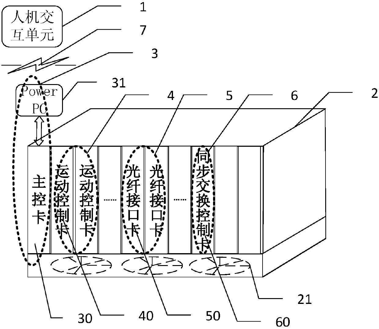
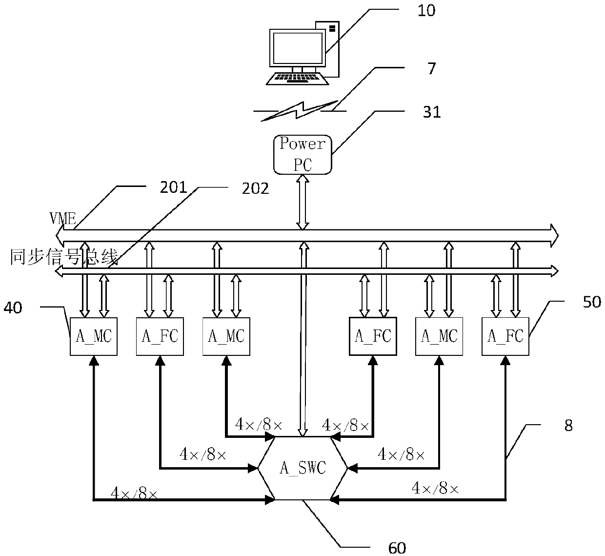
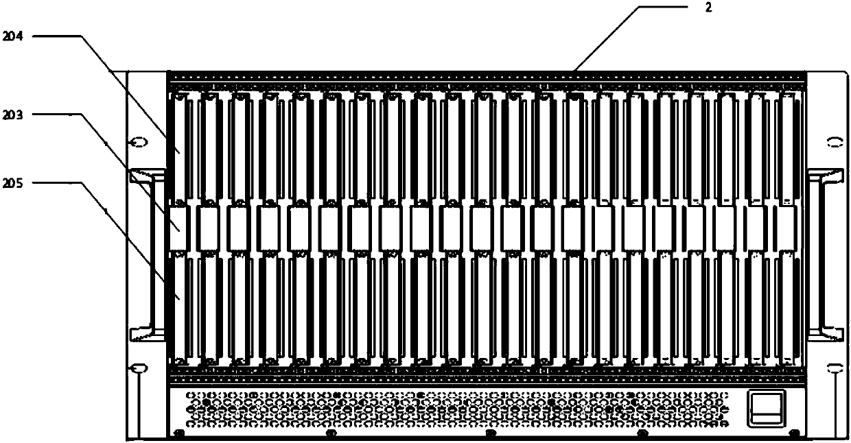
[0044] figure 1 It is the overall framework of the workpiece table motion control system based on the VME-S bus according to the present invention, figure 2 It is a system structure diagram of the present invention. The motion control system includes a human-computer interaction unit 1, a VME bus chassis 2, a CPU main control unit 3, a motion control unit 4, an optical fiber interface unit 5 and a synchronous switching control unit 6;

[0045]The human-computer interaction unit 1 is composed of a host computer 10, a manual operation module and an alarm, and is connected with the main control CPU unit 2 through a TCP / IP network 7, and is used to control the CPU main control unit 3 on the VME bus chassis 2, the motion Control unit 4, optical fiber interface unit 5 and synchronous switching ...


PUM


Abstract

The invention discloses a VME-S bus based working table movement control system, and belongs to the technical field of the movement control system for semiconductors and other precision mechanical equipment. The movement control system comprises a man-machine interaction unit, a VME bus machine case, a CPU main control unit, a movement control unit, an optical fiber interface unit and a synchronous exchange control unit. According to the control system, the dispatching of a RapidIO network, the Ethernet, and a synchronous timing network is completed by a synchronous exchange control card; the signal processing, data processing and other algorithms, as well as data communication are completed by a multi-core DSP movement control card in real time rapidly; and the transceiving, preprocessing and data communication of each path of the optical fiber signals are completed by an optical fiber interface card. According to the VME-S bus based working table movement control system, the multi-DSP processing function is realized by the improved movement control card; in addition, the movement control card is matched with the optical fiber interface card and the synchronous exchange control card to complete flexible application configuration of the system; and meanwhile, the movement control system has relatively high compatibility with other systems and products.

Description

technical field [0001] The invention belongs to the technical field of semiconductor equipment, and relates to a workpiece table motion control system based on a VME-S bus. Background technique [0002] Lithography machine is the core equipment of IC manufacturing industry. With the development and progress of lithography machine and its lithography technology, the control system of lithography machine workpiece table has higher and higher requirements for parallel computing, multi-sensor information fusion, complex motion control algorithm, and real-time control. The bus architecture form, bus bandwidth, system performance requirements, data processing performance, data storage capacity, real-time performance, stability, reliability and energy consumption of the corresponding control system platform put forward more stringent requirements. The bottleneck of the traditional workpiece table motion control system based on VME bus mainly lies in the bus data throughput rate, n...

Claims


Application Information

Patent Timeline
Patent Type & Authority Patents(China)
IPC IPC(8): G03F7/20G05B19/042
CPCG03F7/70725G05B19/0423
Inventor 朱煜成荣黄涛杨开明李鑫廖晨翔王希远穆海华尹文生胡金春梁志敏黄伟才
Owner TSINGHUA UNIV
Learn More