Radial line dielectric resonant antenna array

A technology of dielectric resonant antenna and radial line, which is applied in antenna arrays, antennas, slot antennas, etc., can solve the problems of large number of units, exciting surface waves, and reduced radiation efficiency, and achieves easy processing and mass production, good antenna The effect that performance, arrangement are simple

Inactive Publication Date: 2016-08-17
BEIJING UNIV OF POSTS & TELECOMM
View PDF8 Cites 11 Cited by
  • Summary
  • Abstract
  • Description
  • Claims
  • Application Information

AI Technical Summary

Problems solved by technology

When the feed loss of microstrip line is large and the number of units is large, the feed network is complex
[0004] At present, the commonly used wireless communication high-gain antennas include horn antennas, microstrip antenna arrays, reflectarray antennas, and radial line antennas. Among them, the horn antennas and reflectarray antennas are three-dimensional antennas with large sizes. and dielectric loss, will excite surface waves, resulting in reduced radiation efficiency

Method used


Image

  • Radial line dielectric resonant antenna array
  • Radial line dielectric resonant antenna array
  • Radial line dielectric resonant antenna array

Examples


Embodiment

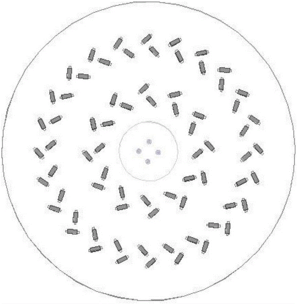
[0040] image 3 The arrangement scheme of the radial line dielectric resonant antenna array radiating circularly polarized electromagnetic waves is shown. Similarly, the arrangement of the dielectric resonant antenna array is the same as the arrangement of the slots of the radial line slot waveguide, and only the arrangement of the slots of the radial line slot waveguide will be described here.

[0041] In this arrangement, the radial line slot waveguide is composed of a series of annularly arranged slot pairs, and each array unit includes two mutually perpendicular slots. The distance between two mutually perpendicular gaps is relatively close. If the center of each gap in a circle is connected to the center of the circle, the angles between the long sides of the gap and the respective centerlines are the same, but the long sides of the gaps in different circles are the same as The included angles of the respective connecting lines may be different.

[0042] A plurality of ...


PUM


Abstract

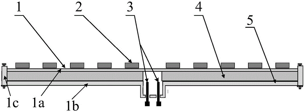
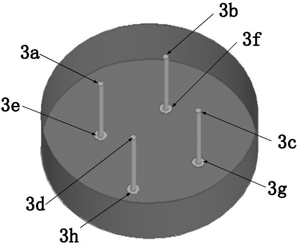
The invention discloses a radial line dielectric resonant antenna array. The radial line dielectric resonant antenna array comprises a radial line seam waveguide, a dielectric resonant antenna array, a feeding part and a dielectric layer, wherein the radial line seam waveguide comprises a metal plate, a metal bottom plate and a metal side wall; the dielectric layer is in the shape of a hollow cylinder, and fills the inside of the radial line seam waveguide; a hollow part is corresponding to a lug boss of the metal bottom plate; the dielectric resonant antenna array comprises a plurality of dielectric resonant antenna units which are positioned right above a seam in the upper surface of the metal plate; a feeding probe part comprises four metal rods and four SMA antenna joints, wherein each metal rod is connected with one SMA antenna joint to form a feeding probe. The radial line dielectric resonant antenna array provided by the invention adopts a four-feed-point feeding mode to radiate circular polarization electromagnetic waves, so that high gain and relatively high aperture efficiency are realized.

Description

technical field [0001] The invention relates to a radial line waveguide dielectric resonant antenna array, in particular to a radial line waveguide dielectric resonant antenna array with four feed points that can be used for wireless communication, and belongs to the technical field of communication antenna arrays. Background technique [0002] The dielectric resonant antenna is a resonant antenna composed of low-loss microwave dielectric materials, and its resonant frequency is determined by the size, shape and relative permittivity of the resonator. Dielectric resonator antennas have good performance and have received extensive attention and research. The dielectric constant of the dielectric resonant antenna can be selected in a wide range, the size and bandwidth can be flexibly controlled, the shape is diversified, the loss is small, and the radiation efficiency is high. The processing technology is simple, the cost is low, and it is easy to integrate with equipment. D...

Claims


Application Information

Patent Timeline
Patent Type & Authority Applications(China)
IPC IPC(8): H01Q13/10H01Q1/38H01Q21/00H01Q21/24
CPCH01Q13/10H01Q1/38H01Q21/00H01Q21/24
Inventor 苏明刘元安石琳余建国黎淑兰于翠屏吴永乐王卫民
Owner BEIJING UNIV OF POSTS & TELECOMM
Why Eureka
Try Eureka