A control method for a single-phase grid-connected inverter and a method for obtaining control parameters thereof
A control method and inverter technology, applied in the direction of single network parallel feeding arrangement, AC network to reduce harmonic/ripple, harmonic reduction device, etc. System calculations and other issues
- Summary
- Abstract
- Description
- Claims
- Application Information
AI Technical Summary
Problems solved by technology
Method used
Image
Examples
Embodiment 1
[0100] A method for controlling a single-phase grid-connected inverter, comprising the following steps:
[0101] Step 1. Through the grid voltage detection link, the grid voltage effective value U is collected and obtained g ;
[0102] Step 2. U g Input the phase-locked loop algorithm link to get the phase angle θ of the grid voltage;
[0103]Step 3. Given the magnitude I of the grid reference current m , using the equation I ref =I m sin(θ) to get the grid current reference value I ref ;
[0104] Step 4.I ref and the current output value I of the grid side inductance obtained by collecting g Subtracting each other, the obtained error E enters the proportional resonance controller and the harmonic compensation controller respectively;
[0105] Step 5. The output of the proportional resonant controller U pr and the output of the harmonic compensation controller U hc Add and compare the resulting sum U ab Perform clipping to obtain the reference value I of the filter...
Embodiment 2
[0146] A specific solution is used to further illustrate the control method of the single-phase grid-connected inverter of the present invention.
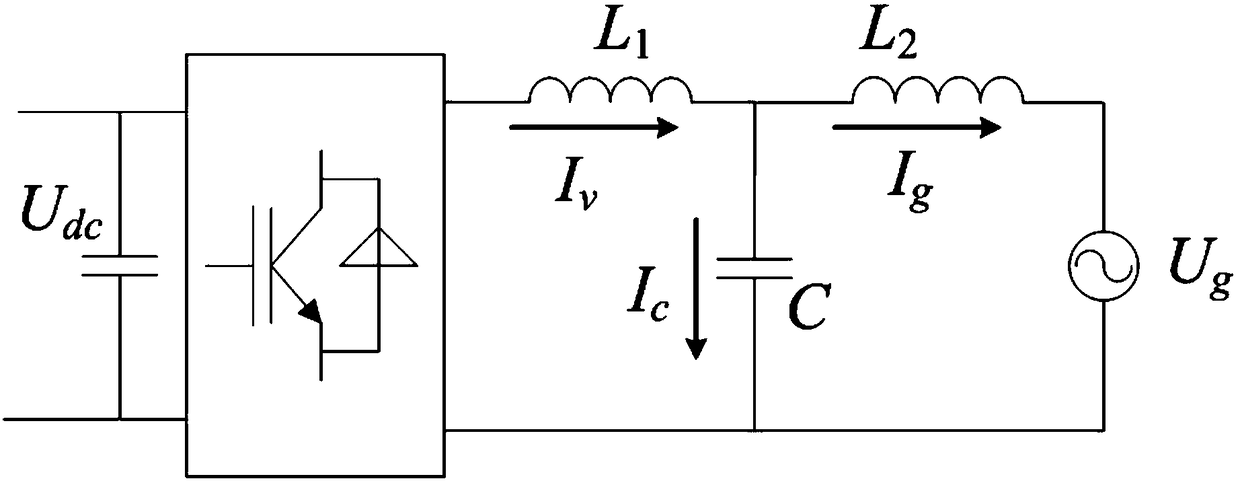
[0147] figure 1 It is a topological structure diagram of a single-phase LCL grid-connected inverter utilizing the control method of the invention. Neglecting the parasitic resistance of the device, L 1 , L 2 and C to form an LCL filter; to simplify the analysis, set the DC bus voltage U dc is a constant; U AB is the output voltage of the inverter bridge; U g is the grid voltage.
[0148] The system parameters of this embodiment are shown in Table 1.
[0149] Table 1 System parameters
[0150]
[0151]
[0152] figure 2 is a control block diagram of a system control method according to an embodiment of the present invention, refer to below figure 2 The composition of the system control method and the functions of each component in this embodiment will be described.
[0153] This embodiment proposes a dual current l...
PUM
 Abstract
Description
Claims
Application Information
 - R&D
- Intellectual Property
- Life Sciences
- Materials
- Tech Scout
- Unparalleled Data Quality
- Higher Quality Content
- 60% Fewer Hallucinations
Browse by: Latest US Patents, China's latest patents, Technical Efficacy Thesaurus, Application Domain, Technology Topic, Popular Technical Reports.
© 2025 PatSnap. All rights reserved.Legal|Privacy policy|Modern Slavery Act Transparency Statement|Sitemap|About US| Contact US: help@patsnap.com


