A reciprocating hydrogen internal cooling end ventilation cooling device for a turbogenerator
A turbogenerator, ventilation and cooling technology, applied in the direction of cooling/ventilation devices, electromechanical devices, electrical components, etc., can solve the problems of copper shielding and pressure ring height, achieve the effect of increasing flow, speeding up fluid speed, and saving materials
- Summary
- Abstract
- Description
- Claims
- Application Information
AI Technical Summary
Problems solved by technology
Method used
Image
Examples
specific Embodiment approach 1
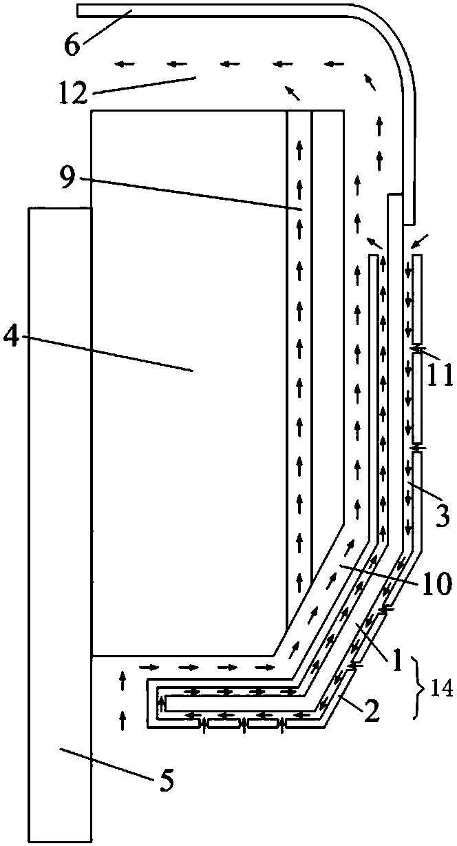
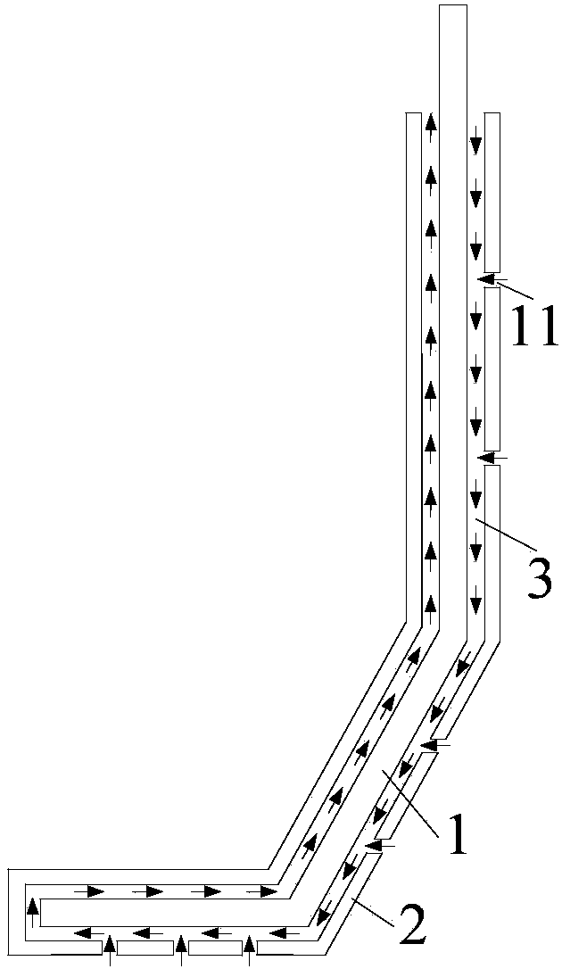
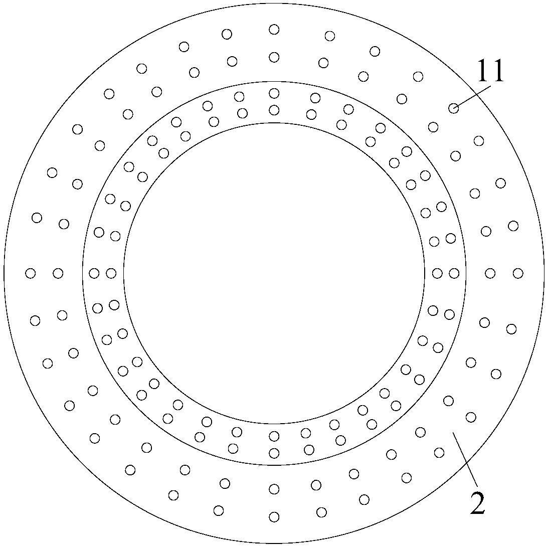
[0026] Specific implementation mode one: combine figure 1 , figure 2 and image 3 Describe this embodiment, the steam turbine generator reciprocating type hydrogen internal cooling end ventilation cooling device according to the present invention includes a pressure finger 5, a pressure ring 4 pressed on the pressure finger 5, and a copper ring fixed on the pressure ring 4. Shield 14, the bow-shaped wind deflector 6 fixed on the outer diameter of the copper shield 14, and the wind guide groove 12 is arranged between the pressure ring 4 and the bow-shaped wind deflector 6, and the copper shield 14 includes an inner core copper shield 1 and an outer copper shield 1. Shielding 2, the inner core copper shielding 1 is arranged in the cavity of the outer copper shielding 2, and its outer diameter end is fixedly connected with the bow-shaped wind deflector 6, the air duct between the inner core copper shielding 1 and the inner wall of the outer copper shielding 2 is Reciprocating ...
specific Embodiment approach 2
[0031] Specific implementation mode two: combination figure 2 , image 3 , Figure 4 This embodiment is described. The difference between this embodiment and Embodiment 1 is that it also includes a vacuum chamber 7, the vacuum chamber 7 is set inside the pressure ring 4 adjacent to the inner diameter of the pressure ring, and the inner wall of the vacuum chamber 7 is set There is a heat-reflecting layer 8 . There is no anti-heat layer 8 on the inner wall of the vacuum chamber 7 close to the inner diameter of the pressure ring. The vacuum cavity 7 in the press ring 4 can greatly hinder the heat flow in the inner diameter area of the press ring 4 to the inside of the press ring 4 and the press finger 5 . The aluminum foil layer on the wall of the vacuum chamber 7 constitutes the heat-reflecting layer 8, which can effectively reflect heat radiation and reduce the heat radiated from the inner diameter area of the pressure ring 4 to the inside of the pressure ring 4 and the...
specific Embodiment approach 3
[0033] Specific implementation mode three: combination figure 2 , image 3 , Figure 5 This embodiment is described. The difference between this embodiment and the second embodiment is that the section of the vacuum chamber 7 along the radial direction is "L"-shaped, and the anti-heat layer 8 is closely attached to the wall of the "L"-shaped vacuum chamber 7 . The vacuum chamber 7 with an "L"-shaped cross section has a larger contact area with the pressure ring 4, which can further hinder the flow of heat in the inner diameter area of the pressure ring 4 to the inside of the pressure ring 4 and the pressure finger 5. Other specific implementation manners are the same as the second implementation manner, and details are not repeated here.
PUM
 Abstract
Description
Claims
Application Information
 - R&D
- Intellectual Property
- Life Sciences
- Materials
- Tech Scout
- Unparalleled Data Quality
- Higher Quality Content
- 60% Fewer Hallucinations
Browse by: Latest US Patents, China's latest patents, Technical Efficacy Thesaurus, Application Domain, Technology Topic, Popular Technical Reports.
© 2025 PatSnap. All rights reserved.Legal|Privacy policy|Modern Slavery Act Transparency Statement|Sitemap|About US| Contact US: help@patsnap.com


