
Rectification control circuit for bidirectional CLLLC resonant converter

A resonant converter and control circuit technology, applied in the direction of converting DC power input to DC power output, AC power input converting to DC power output, control/regulation system, etc., can solve the problem of increasing rectification loss, hindering power, and structural asymmetry and other problems to achieve the effect of improving the overall efficiency and reducing the rectification loss.

Inactive Publication Date: 2016-08-17
SOUTH CHINA UNIV OF TECH
View PDF5 Cites 31 Cited by
  • Summary
  • Abstract
  • Description
  • Claims
  • Application Information

AI Technical Summary

Problems solved by technology

The transmission power of the traditional DAB topology changes with the change of the phase shift angle, and the realization range of soft switching is also affected by the load change. The CLLC resonant topology studied in recent years has an asymmetric structure and asymmetrical secondary side when it works in forward and reverse directions. Complete resonance hinders power transmission, CLLLC resonant topology uses diode rectification on the power receiving side, which increases rectification loss

Method used


Image

  • Rectification control circuit for bidirectional CLLLC resonant converter
  • Rectification control circuit for bidirectional CLLLC resonant converter
  • Rectification control circuit for bidirectional CLLLC resonant converter

Examples


Embodiment Construction

[0016] The present invention will be further described in detail below in conjunction with the embodiments and the accompanying drawings, but the embodiments of the present invention are not limited thereto. It should be pointed out that if the control process is not specifically described in detail, it is all realized or understood by those skilled in the art with reference to the prior art (for example, the description about the lead switch tube and the lag switch tube in the full bridge circuit of the bidirectional CLLLC resonant converter There is no need to go into details, and there is no need to separately name and describe each switching tube).

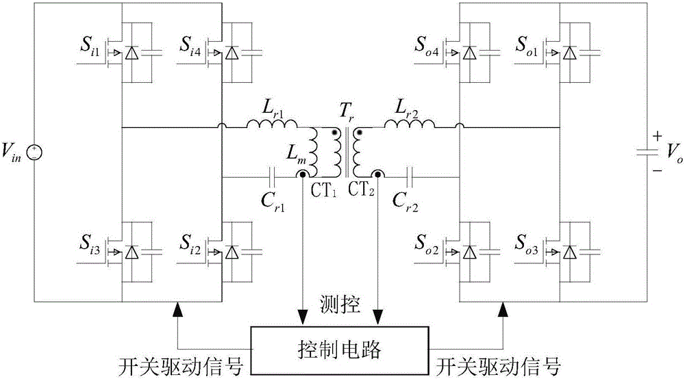
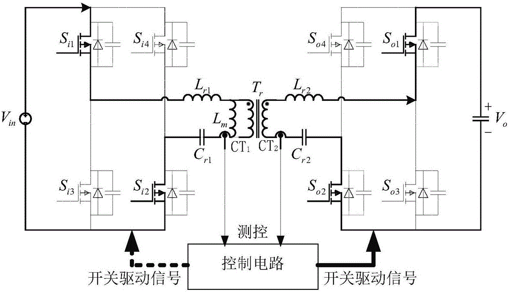
[0017] Such as figure 1 As shown, it is a rectification control schematic diagram for a bidirectional CLLLC resonant converter of the present invention, including a power supply V in , load V o , four primary side switches (S i1 -S i4 ), four secondary side switches (S o1 -S o4 ), primary side resonant inductance L r1 ,...


PUM


Abstract

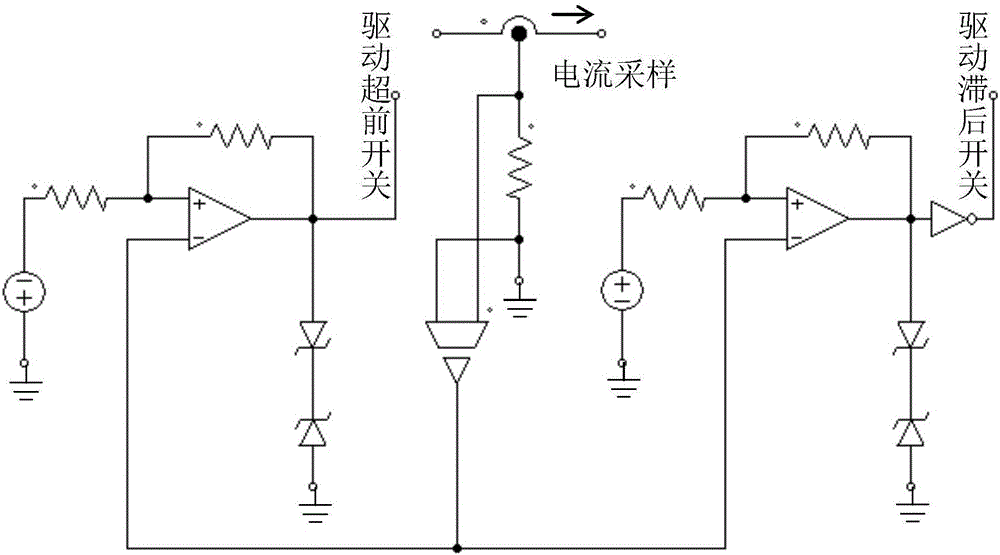
The invention discloses a rectification control circuit for a bidirectional CLLLC resonant converter. Both the primary side and the secondary side of the transformer in the bidirectional CLLLC resonant converter are connected to a current transformer, and the current on the power receiving side of the transformer is sampled, and It is converted into a voltage signal through a unit resistance, and connected to the inverting input terminals of two hysteresis comparators through a voltage sensor. The output signals of the two hysteresis comparators respectively drive the leading switch and the lagging switch on the power receiving side to realize MOSFET rectification. Since the on-resistance of the MOSFET is very small, the rectification control circuit for the bidirectional CLLLC resonant converter of the present invention reduces the rectification loss and improves the overall efficiency of the converter compared with diode rectification.

Description

technical field [0001] The invention relates to the field of bidirectional DC-DC converters, in particular to a rectification control circuit for a bidirectional CLLLC resonant converter. Background technique [0002] Bidirectional DC-DC converters can realize the functions of DC transformation, bidirectional energy transmission and electrical isolation, and have been widely used in fields such as electric vehicles, renewable energy, DC power distribution systems, uninterruptible power systems, and power electronic transformers. Whether to achieve high power density and high conversion efficiency has always been the focus and difficulty of DC-DC converter design. The transmission power of the traditional DAB topology changes with the change of the phase shift angle, and the realization range of soft switching is also affected by the load change. The CLLC resonant topology studied in recent years has an asymmetric structure and asymmetrical secondary side when it works in for...

Claims


Application Information

Patent Timeline
IPC IPC(8): H02M3/335H02M7/219
CPCH02M3/33584H02M7/219
Inventor 杜贵平温先佳
Owner SOUTH CHINA UNIV OF TECH
Learn More