Single-phase AC-DC/DC-AC dual-purpose circuit and three-phase AC-DC/DC-AC dual-purpose circuit
A DC-AC and circuit technology, applied in the field of single-phase or three-phase AC-DC/DC-AC dual-purpose circuits, can solve problems such as low efficiency, inability to be used as a DC-AC inverter, and large overall loss, and achieve The effect of high power density, low cost, and small number of components
- Summary
- Abstract
- Description
- Claims
- Application Information
AI Technical Summary
Problems solved by technology
Method used
Image
Examples
Embodiment 1
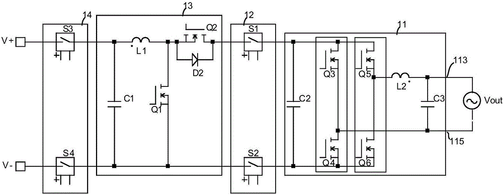
[0033] see figure 1 , the single-phase AC-DC / DC-AC dual-purpose circuit in the preferred embodiment of the present invention includes a PFC converter module 11, an intermediate level protection module 12, a non-isolated step-up / step-down module 13 and input and output protection modules connected in series. Module 14.
[0034] The PFC converter module 11 includes a first bridge arm 112, a second bridge arm 114, a filter capacitor C1 and an energy storage inductor L1; the first bridge arm 112, the second bridge arm 114 and the filter capacitor C1 connected in parallel; the first bridge arm 112 includes two main switch tubes Q1 and Q2 connected in series in the same direction, and the second bridge arm 114 includes two rectifier tubes Q3 and Q4 connected in series in the same direction; the energy storage inductor L1 One end is connected to the series node of the two main switching transistors Q1 and Q2, the other end is used as the first AC port 113, and the series node of the...
Embodiment 2
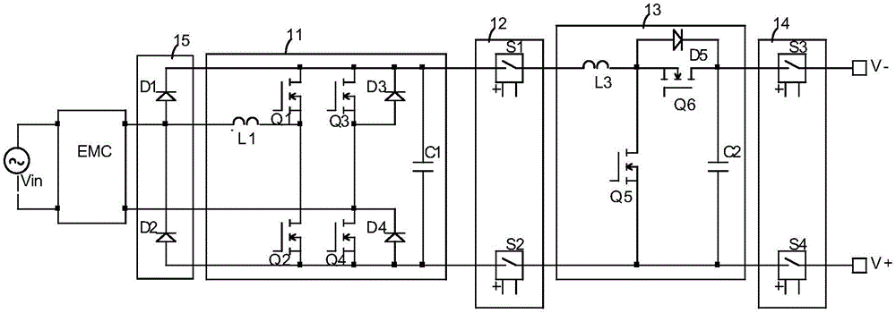
[0041] Another advantage of this technical solution is that energy can flow in both directions and can be used as a DC-AC inverter. Please refer to figure 2 , the non-isolated step-up / step-down module 13 here takes a Boost step-up converter as an example, and the Boost converter boosts an input voltage of, for example, 200Vdc to 400Vdc to another high voltage of 420Vdc. The PFC converter module 11 (serving as an inverter at this time) can adopt a SPWM (Sinusoidal Pulse Width Modulation, sinusoidal pulse width modulation) control method to invert the direct current output by the Boost converter into an alternating current output. If the main switching tube Q1 of the non-isolated boost / buck module 13 is short-circuited, the input and output protection module 14 cuts off the input side and the non-isolated boost / buck module 13 in time. If the main switching tubes Q3 to Q6 of the PFC converter module 11 are short-circuited, the intermediate protection module 12 can disconnect the...
Embodiment 3
[0043] see image 3 , if the non-isolated step-up / step-down module 13 adopts a Boost step-up converter, then there is image 3 The technical solution shown. For occasions where the efficiency requirement is not high, the freewheeling tube Q6 can use a rectifier diode, such as an ultra-fast recovery rectifier diode or a SiC diode. If a high-voltage rectifier is used, the traditional Si process MOSFET has disadvantages such as poor body diode reverse recovery characteristics and large junction capacitance, and the freewheeling tube Q6 should use a GaN Transistor switching device or a SiC MOSFET. A simple realization scheme of the protection stage is to short-circuit the protection switch S2 in the intermediate protection module 12 and the protection switch S4 of the input and output protection module 14, and use MOSFETs, relays, fuses, etc. for the protection switches S1 and S3. In the event of a short-circuit fault in the main switching tube Q5 , the protection switch S1 is t...
PUM
 Abstract
Description
Claims
Application Information
 - R&D
- Intellectual Property
- Life Sciences
- Materials
- Tech Scout
- Unparalleled Data Quality
- Higher Quality Content
- 60% Fewer Hallucinations
Browse by: Latest US Patents, China's latest patents, Technical Efficacy Thesaurus, Application Domain, Technology Topic, Popular Technical Reports.
© 2025 PatSnap. All rights reserved.Legal|Privacy policy|Modern Slavery Act Transparency Statement|Sitemap|About US| Contact US: help@patsnap.com


