Double-working mode acoustic liner for broadband noise suppression and control method
A double-working mode and noise suppression technology, which is applied to transducer circuits, sensors, electrical components, etc., can solve the problems that the acoustic lining cannot effectively suppress noise, the system is large in size, and the dynamic response is slow, so as to facilitate system integration and small size The effects of sizing, widening the frequency band range, and frequency bandwidth
- Summary
- Abstract
- Description
- Claims
- Application Information
AI Technical Summary
Problems solved by technology
Method used
Image

Examples
Embodiment 1
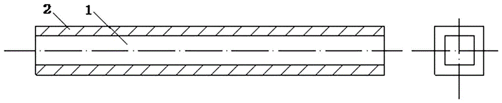
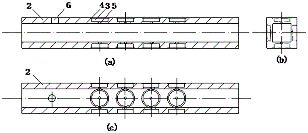
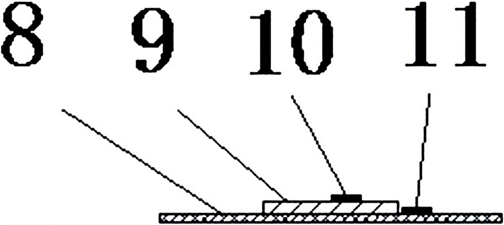
[0028] Embodiment 1: as Figure 1-4 As shown in the figure, an acoustic lining with dual working modes for broadband noise suppression includes an acoustic pipeline 1 with an array of annular grooves around it, the center of the acoustic pipeline 1 is perforated for the acoustic lining, and the front end of the acoustic pipeline 1 is provided with a microphone mounting hole 6, and the microphone A microphone 7 is installed in the installation hole 6; a resonant cavity 3 is arranged at intervals on the wall of the acoustic pipeline 1, the bottom of the resonant cavity 3 is provided with a spout 5 to the perforation of the acoustic lining, and the top of the resonant cavity 3 is provided with a bonding groove 4, and the top of the bonding groove 4 is bonded A vibrating diaphragm 8, a piezoelectric material 9 is installed on the vibrating diaphragm 8, an upper electrode 10 and a lower electrode 11 are respectively installed on the top and side walls of the piezoelectric material 9...
experiment example 1
[0037] Experimental Example 1: Piezoelectric acoustic lining works in the volume adjustment mode (static mode): the thickness of the nozzle 5 is 3mm, the diameter is 1mm, the depth of the resonant cavity 3 is 1mm, and the diameter of the resonant cavity 3 is 35mm. According to the formula (1), the acoustic The resonance frequency at this time is f 0 =720Hz.
[0038] A direct current within 30V is passed between the upper electrode and the lower electrode of the piezoelectric material, and the piezoelectric material deforms, driving the vibrating diaphragm to deform upward or downward, and the volume of the cavity changes accordingly to realize the adjustment of the resonance frequency. The transmission loss of the system at this time is obtained through the measurement of the microphone, and the frequency corresponding to the maximum value of the transmission loss is the resonance frequency f of the piezoelectric acoustic lining 0 . Record the magnitude of the applied DC vol...
experiment example 2
[0041] Experimental example 2: Piezoelectric acoustic lining works in volume adjustment mode (static mode): the thickness of the nozzle 5 is 3mm, the diameter is 1mm, the depth of the resonant cavity 3 is 1mm, and the diameter is 35mm. The resonance frequency of the acoustic lining is calculated according to formula (1) for f 0 =720Hz.
[0042] The working conditions of the piezoelectric acoustic lining are as follows: Figure 6 . When the frequency f of airflow noise 13 12 =726 Hz, the acoustic lining works in volume adjustment (static mode), which is greater than the resonance frequency f of the acoustic lining resonant cavity 3 0 (i.e. f 12 > f 0 ),Inquire Figure 8 , find the voltage value corresponding to 726Hz. , input a -15V DC voltage between the upper electrode 10 and the lower electrode 11 of the acoustic liner, and the piezoelectric material 9 shrinks and deforms after being driven by the negative voltage, driving the vibrating diaphragm 8 to be concave, resu...
PUM
 Abstract
Description
Claims
Application Information
 - R&D
- Intellectual Property
- Life Sciences
- Materials
- Tech Scout
- Unparalleled Data Quality
- Higher Quality Content
- 60% Fewer Hallucinations
Browse by: Latest US Patents, China's latest patents, Technical Efficacy Thesaurus, Application Domain, Technology Topic, Popular Technical Reports.
© 2025 PatSnap. All rights reserved.Legal|Privacy policy|Modern Slavery Act Transparency Statement|Sitemap|About US| Contact US: help@patsnap.com