An energy-saving wet desulfurization device and process method

A technology of wet desulfurization and process method, applied in the field of coal chemical industry, can solve problems such as waste

Active Publication Date: 2018-12-28
江西心连心化学工业有限公司 +2
View PDF3 Cites 0 Cited by
  • Summary
  • Abstract
  • Description
  • Claims
  • Application Information

AI Technical Summary

Problems solved by technology

There is a large pressure difference before and aft...

Method used


Image

  • An energy-saving wet desulfurization device and process method
  • An energy-saving wet desulfurization device and process method

Examples


Embodiment 1

[0029] A process method of an energy-saving wet desulfurization device, comprising the following steps:

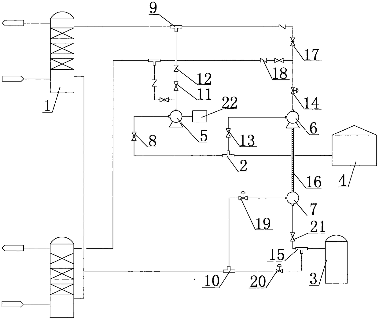
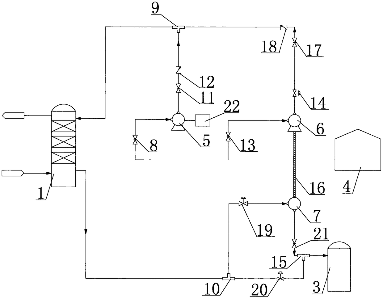
[0030] Step 1: The desulfurized lean liquid in the lean liquid tank 4 is divided into two parts, one part enters several desulfurization towers 1 through the energy recovery unit, and the other part enters several desulfurization towers 1 through the energy replenishment unit; the desulfurization lean liquid The liquid components are sodium carbonate, sodium metavanadate, baking gel and water, and the temperature of the desulfurized poor liquid is 30°C;

[0031] Step 2: When the desulfurized lean liquid in the energy recovery unit and the energy replenishment unit enters the desulfurization tower 1 and contacts the shift gas countercurrently, absorbs the hydrogen sulfide in the shift gas to become a desulfurization rich liquid; the desulfurization rich liquid passes through the desulfurization tower 1 The pressure behind the bottom liquid outlet is 1.5MPa;

[0032] Step 3...

Embodiment 2

[0034] A process method of an energy-saving wet desulfurization device, comprising the following steps:

[0035] Step 1: The desulfurized lean liquid in the lean liquid tank 4 is divided into two parts, one part enters several desulfurization towers 1 through the energy recovery unit, and the other part enters several desulfurization towers 1 through the energy replenishment unit; the desulfurization lean liquid The liquid components are sodium carbonate, sodium metavanadate, baking gel and water, and the temperature of the desulfurized poor liquid is 50°C;

[0036] Step 2: When the desulfurized lean liquid in the energy recovery unit and the energy replenishment unit enters the desulfurization tower 1 and contacts the shift gas countercurrently, absorbs the hydrogen sulfide in the shift gas to become a desulfurization rich liquid; the desulfurization rich liquid passes through the desulfurization tower 1 The pressure behind the bottom liquid outlet is 2.4MPa;

[0037] Step 3...

Embodiment 3

[0039] A process method of an energy-saving wet desulfurization device, comprising the following steps:

[0040] Step 1: The desulfurized lean liquid in the lean liquid tank 4 is divided into two parts, one part enters several desulfurization towers 1 through the energy recovery unit, and the other part enters several desulfurization towers 1 through the energy replenishment unit; the desulfurization lean liquid The liquid components are sodium carbonate, sodium metavanadate, baking gel and water, and the temperature of the desulfurized poor liquid is 40°C;

[0041] Step 2: When the desulfurized lean liquid in the energy recovery unit and the energy replenishment unit enters the desulfurization tower 1 and contacts the shift gas countercurrently, absorbs the hydrogen sulfide in the shift gas to become a desulfurization rich liquid; the desulfurization rich liquid passes through the desulfurization tower 1 The pressure behind the bottom liquid outlet is 1.95MPa;

[0042] Step ...


PUM


Abstract

The invention belongs to an energy-saving type wet-process desulfurization device and a process method. The energy-saving type wet-process desulfurization device comprises a lean liquid groove, wherein the lean liquid groove is respectively connected with an energy recovering unit and an energy supplementing unit by a first three-way joint; the energy recovering unit and the energy supplementing unit are respectively connected with a liquid inlet pipeline in at least one desulfurization tower device; a liquid outlet at the bottom of the desulfurization tower is connected with a first adjusting valve, a turbine, a second adjusting valve and a flashing evaporation groove in sequence by pipelines; the energy recovering unit comprises a first gate valve connected with a second end of the first three-way joint; the first gate valve is connected with a third adjusting valve by a lean liquid pump in the energy recovering unit; and the lean liquid pump in the energy recovering unit is connected with a power output end of the turbine by a seat type clutch. The energy-saving type wet-process desulfurization device and the process method have the advantages that the equipment structure is simple, the process flow design is reasonable, the investment is less and the efficiency is high.

Description

technical field [0001] The invention belongs to the technical field of coal chemical industry, and in particular relates to an energy-saving wet desulfurization device and a process method. Background technique [0002] A hydraulic turbine is an energy recovery device; a turbine is a machine that converts the energy contained in a fluid working medium into mechanical energy, also known as a turbine. The energy possessed by the fluid is converted into kinetic energy when passing through the nozzle in the flow, and when the fluid flows through the impeller, the fluid impacts the blades and pushes the impeller to rotate, thereby driving the turbine shaft to rotate. The turbine shaft drives other machinery directly or through the transmission mechanism to output mechanical work. The working medium of turbomachinery can be liquid, steam, gas, air and other gases or mixed gases. A turbine that uses liquid as a working fluid is called a hydraulic turbine. [0003] There are thre...

Claims


Application Information

Patent Timeline
IPC IPC(8): B01D53/96B01D53/78B01D53/52
CPCB01D53/52B01D53/78B01D53/96B01D2251/304B01D2251/60B01D2251/606B01D2258/0283
Inventor 段艳慧张洋洋孙帅吴培袁凤慧段东林刘磊李媛媛
Owner 江西心连心化学工业有限公司
Why Eureka
Try Eureka