
Cyclone separation type biomass gasifying device

A gasification device and cyclone separation technology, applied in the field of biomass gasification equipment, can solve the problems of large amount of gasification agent and low calorific value of gas production, and achieve the effects of increasing surface area, prolonging residence time, and high-efficiency gas-solid separation

Inactive Publication Date: 2016-08-24
胥利先
View PDF12 Cites 2 Cited by
  • Summary
  • Abstract
  • Description
  • Claims
  • Application Information

AI Technical Summary

Problems solved by technology

[0004] The main purpose of the present invention is to design a cyclone with high calorific value for gas production in view of the defects that the existing biomass gasification device requires a large amount of gasification agent (air, oxygen, etc.) and the calorific value of gas production is not high. Separate biomass gasification device

Method used


Image

  • Cyclone separation type biomass gasifying device
  • Cyclone separation type biomass gasifying device

Examples


Embodiment Construction

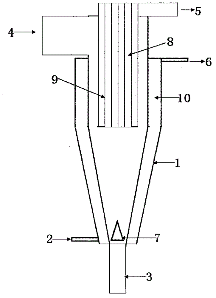
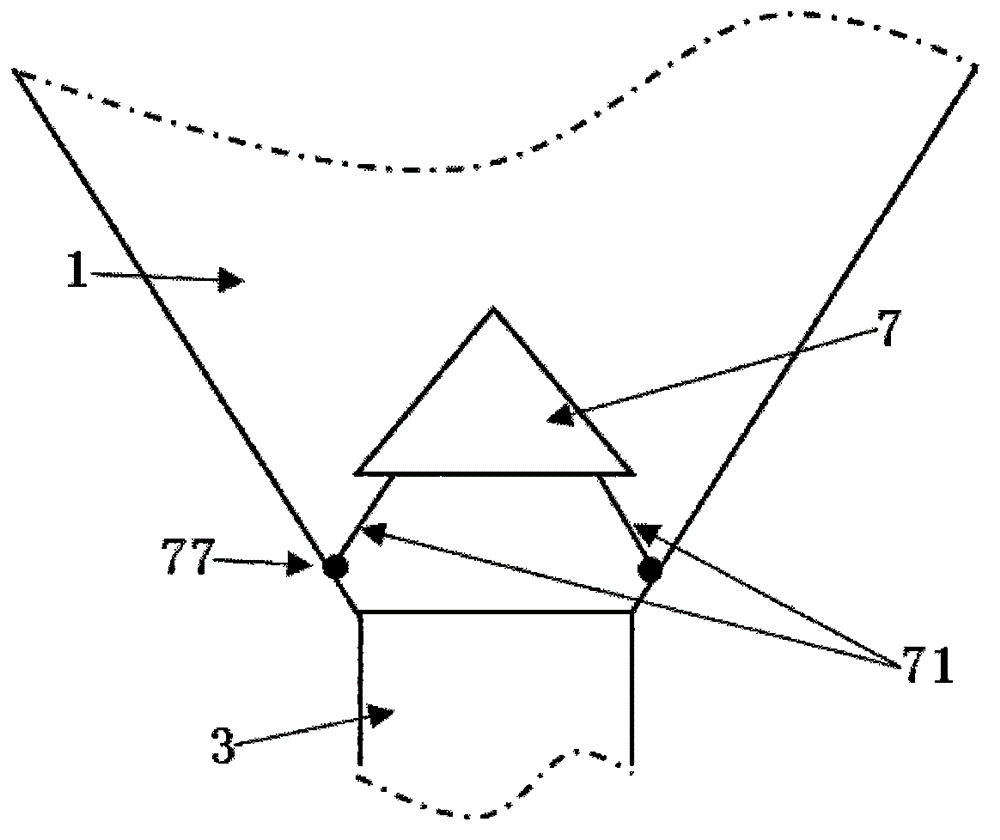
[0027] As shown in the figure, the cyclone-separated biomass gasification device of the present invention has a cylindrical cylinder at the top and a conical cylinder at the bottom, with an inner heating barrier 10 and an outer heat insulation layer. The hot air inlet 2 communicated with the jacket space of the heating compartment 10 and the downward discharge port 3 communicated with the inner space of the reactor main body 1, and the upper end of the reactor main body 1 has biomass communicated with the inner space of the reactor main body 1 The heat carrier and gasification agent inlet 4, the clean combustible gas outlet 5, and the hot gas flow outlet 6 communicated with the jacket space of the heating compartment 10. The inlet 4 for biomass, heat carrier and gasification agent is equipped with a blower; preferably, the cylindrical barrel and the conical barrel are cylindrical barrel and conical barrel respectively. The biomass, heat carrier and gasification agent inlet 4 c...


PUM


Abstract

The invention relates to a cyclone separation type biomass gasifying device, and aims to solve the problem that the caloric value of produced gas is low. The device comprises a reactor body, the upper part of the reactor body is in a cylindrical shape, the lower part of the reactor body is in a conical shape, the reactor body is provided with an inner heating interlayer and an outer thermal insulation layer; a hot air flow inlet that is communicated with the jacket of the heating interlayer and a downward discharge opening that is communicated with the interior of the reactor body stretch from the lower end of the reactor body; and the upper end of the reactor body is provided with a biomass, hot carrier, and gasifying agent inlet and a clean combustible gas outlet that are communicated with the interior of the reactor body, and a hot air flow outlet that is communicated with the jacket of the heating interlayer. The upper part of the reactor body is provided with a gas outlet channel, a precious metal catalyst is loaded on the inner wall of the gas outlet channel, the upper end of the gas outlet channel is connected to the clean combustible gas outlet; the biomass, hot carrier, and gasifying agent inlet is communicated with the gap between the inner wall of the upper end of the reactor body and the outer wall of the gas outlet channel; and the hot air flow outlet is communicated with the jacket of the heating interlayer of the upper port of reactor body. The biomass, hot carrier, and gasifying agent inlet is provided with a blower, and the cylindrical cylinder and the conical cylinder are cylinder and cone. The provided device has the advantages of high gasifying speed and high caloric value of produced gas.

Description

technical field [0001] The invention relates to biomass gasification equipment, in particular to a cyclone separation type biomass gasification device. Background technique [0002] With the increasing demand for energy, fossil fuels as the main energy are rapidly decreasing, and the use of a large number of fossil fuels has led to global warming and SO x and NO x Emissions increased, seriously polluting the atmosphere. Actively developing and utilizing renewable energy that is conducive to improving the environment is crucial to improving energy shortages and environmental pollution. Renewable energy includes wind power, solar energy, hydropower, biomass energy, hydrogen energy, etc., and biomass is a relatively stable renewable resource. It is the fourth largest energy after coal, oil, natural gas and other fossil energy sources, accounting for 14% of world energy consumption. Biomass can be converted into fuel through various conversion methods, such as carbonization,...

Claims


Application Information

Patent Timeline
IPC IPC(8): C10J3/48C10J3/84
Inventor 胥利先
Owner 胥利先
Learn More