RC oscillator

A technology of oscillators and field effect tubes, applied in the field of RC oscillators, can solve the problems of increasing the circuit area of ​​RC oscillators and tape-out costs, the error of RC oscillator output frequency, increasing the power consumption and area of ​​circuits, etc., and achieves a simple structure , periodic signal stabilization, and the effect of reducing the temperature coefficient

Inactive Publication Date: 2016-08-24
IPGOAL MICROELECTRONICS (SICHUAN) CO LTD
View PDF5 Cites 4 Cited by
  • Summary
  • Abstract
  • Description
  • Claims
  • Application Information

AI Technical Summary

Problems solved by technology

[0006] As mentioned above, in the existing RC oscillator circuit, two comparators AMPa and AMPb are required, and each comparator requires a certain amount of DC current for biasing, and two capacitors C1 and C2 are required for charging and discharging. thus increasing the power consumption and area of ​​the entire circuit
In addition, in the prior art, if the capacitors C1 and C2 are realized by MOS capacitors, since the gate-source voltage varies from 0 to the VREF node voltage during the charging and discharging process, since the threshold voltage of the MOS capacitors is between 0 and VREF Between the node voltages, it will switch continuously between the cut-off zone and the linear zone, so that its capacitance value will be greatly affected by the voltage at both ends, thus causing errors in the output frequency of the RC oscillator; on the other hand, if the capacitors C1 and C2 Using linear capacitors such as MIM capacitors or MOM capacitors to achieve, will increase the area and tape-out cost of the entire RC oscillator circuit

Method used


Image

  • RC oscillator
  • RC oscillator
  • RC oscillator

Examples


Embodiment Construction

[0023] Embodiments of the present invention will now be described with reference to the drawings, in which like reference numerals represent like elements. As mentioned above, the present invention provides an RC oscillator. The RC oscillator of the present invention reduces the number of required comparators and capacitors, saves power consumption and circuit area.

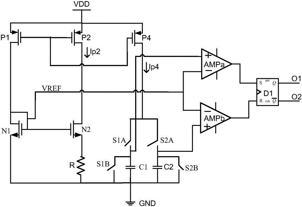
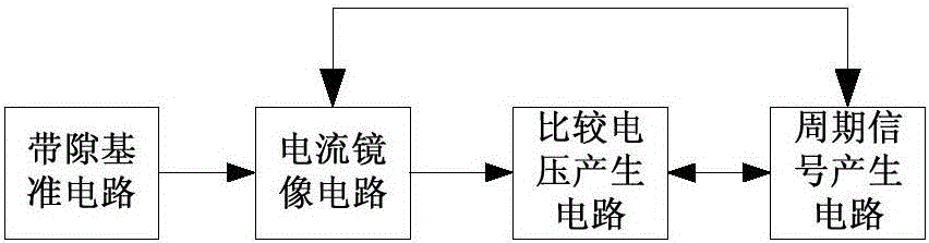
[0024] Please refer to figure 2 , figure 2 It is a structural block diagram of the RC oscillator of the present invention. Such as figure 2 As shown, the RC oscillator of the present invention includes a bandgap reference circuit, a current mirror circuit, a comparison voltage generation circuit and a periodic signal generation circuit; the bandgap reference circuit is connected with the current mirror circuit and an external power supply, and the bandgap reference circuit In order to produce a stable current with a positive temperature coefficient; the current mirror circuit is also connected to the compar...


PUM


Abstract

The invention discloses an RC oscillator comprising a band gap reference circuit, a current mirror circuit, a comparison voltage generating circuit, and a periodic signal generating circuit. The band gap reference circuit is connected with the current mirror circuit and an external power supply, and the band gap reference circuit is used to generate the current provided with the positive temperature coefficient. The current mirror circuit is also respectively connected with the comparison voltage generating circuit and the periodic signal generating circuit, and the current mirror circuit is used to mirror the current generated by the band gap reference circuit to the periodic signal generating circuit. The comparison voltage generating circuit is also connected with the periodic signal generating circuit, and is used to generate the comparison voltage according to the current of the current mirror circuit, and the voltage can be input in the periodic signal generating circuit. The periodic signal generating circuit is used to output the periodic oscillation signal according to the input voltage and the input current. The RC oscillator is advantageous in that the structure is simple, the number of the required comparators and capacitors can be reduced, the power consumption can be reduced, the circuit area can be saved, and the influence of the comparator input imbalance on the oscillator output frequency can be eliminated.

Description

technical field [0001] The present invention relates to the field of integrated circuits, more specifically to an RC oscillator Background technique [0002] The circuit of the existing RC oscillator such as figure 1 Shown: [0003] In the existing RC oscillator, a current source circuit is formed by MOS transistors N1, N2, P1, P2 and resistor R, and the current source circuit generates a DC current Ip2; MOS transistors P2 and P4 constitute a current mirror, and the current The mirror mirrors the current Ip2 into Ip4, thereby forming a charging and discharging current for the capacitors C1 and C2. Wherein, Ip2 and Ip2 are direct currents flowing through the MOS transistors P2 and P4 respectively. [0004] When the existing RC oscillator works, it is divided into two states. In state one, the switches S1A and S2B are closed, and the switches S2A and S1B are disconnected. At this time, the current Ip4 charges the capacitor C1, and the potential of the capacitor C1 graduall...

Claims


Application Information

Patent Timeline
Patent Type & Authority Applications(China)
IPC IPC(8): H03B5/04
CPCH03B5/04
Inventor 何力
Owner IPGOAL MICROELECTRONICS (SICHUAN) CO LTD
Why Eureka
Try Eureka