Device for cleaning summer sleeping mats and other articles

A technology for articles and mats, applied in the field of cleaning devices, can solve the problems of unfavorable health, troublesome cleaning of carpet dirt and color stains, and insufficient cleaning, and achieves the effect of occupying less space

Active Publication Date: 2016-08-31
临泉县白良电子信息技术有限责任公司
6 Cites 7 Cited by

AI-Extracted Technical Summary

Problems solved by technology

When some factories and schools have a lot of people and there is no place to clean the mats, people can only wipe and dry the mats, but this is always not thorough enough to clean; especially when the mats that have been stored for half a year are taken out in summer It is not enough to just wipe and dry, and some bacteria and viruses will remain in the gaps...

Abstract

A device for cleaning summer sleeping mats and other articles is provided with an air inflation water channel with a water drainage pipe. A first sliding way, a second sliding way, a first crosspiece and a second crosspiece are arranged on the top of a rack connected with the water channel. Pulleys on two water pipes are connected with the first sliding way and the second sliding way. The water pipes are provided with handles, spray heads and brushes, and the water pipes are connected with a water inlet pipe through a soft pipe, wherein the water inlet pipe is provided with a cleaning solution tank and a valve. Vertical pipes on the first crosspiece and the second crosspiece are provided with spanners, snap joints, clamping shafts, springs and shaft rods with cross shafts. A third crosspiece and a fourth crosspiece on the front side and the back side of the rack are provided with longitudinal pieces, and the longitudinal pipes are provided with spanners, snap joints, clamping shafts, springs and shaft rods with cross shafts. Rack pieces on the two sides of the rack are provided with a first rotary shaft and a second rotary shaft, wherein the first rotary shaft and the second rotary shaft are provided with a first roller, a second roller and a rotary table. A sliding way embedded in the rack pieces is provided with a bearing, and the bearing is connected with the first rotary shaft. A push-pull rod movably connected with the first rotary shaft is movably connected with a threaded rod, and a nut connected with the threaded rod is arranged on the rack. The rack is provided with a waterproof cover and a leaching device. Clearances are reserved between the first roller and the brush above the first roller, between the second roller and the brush above the second roller and between the cross shafts.

Application Domain

Carpet cleanersFloor cleaners +3

Technology Topic

Scrub brushesWater pipe +6

Image

  • Device for cleaning summer sleeping mats and other articles
  • Device for cleaning summer sleeping mats and other articles
  • Device for cleaning summer sleeping mats and other articles

Examples

  • Experimental program(1)

Example Embodiment

[0021] The present invention will be further described with reference to the drawings.
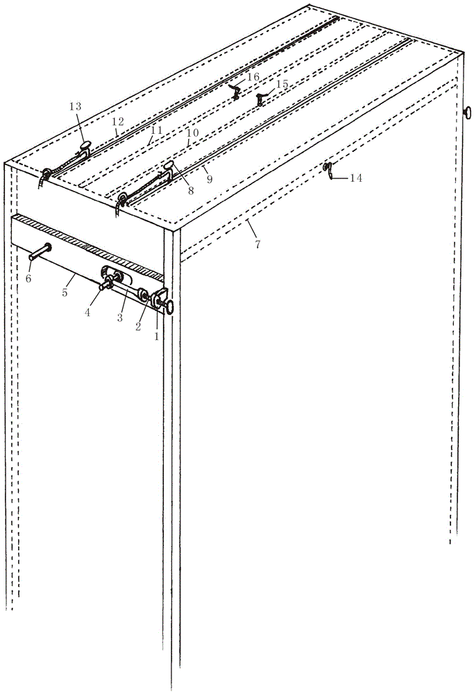
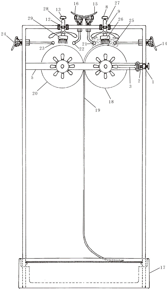
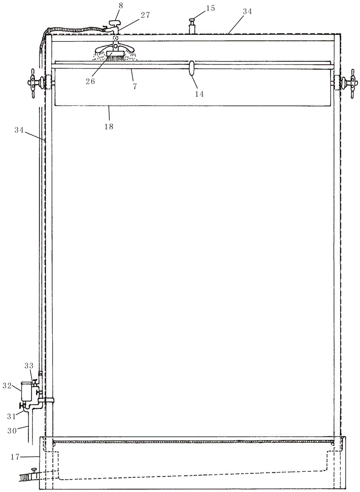
[0022] Such as Figure 1-4 As shown in the figure, 1. nut, 2. screw, 3. push-pull rod, 4. first shaft, 5. left side frame, 6. second shaft, 7. third rail, 8. first handle, 9 .The first slide, 10. The first rail, 11. The second rail, 12. The second slide, 13. The second handle, 14. The third wrench, 15. The first wrench, 16. The second wrench , 17. Sink, 18. First roller, 19. Summer mat, 20. Second roller, 21. First horizontal axis, 22. Second horizontal axis, 23. Fourth horizontal axis, 24. Fourth wrench, 25. The third horizontal axis, 26. The first brush, 27. The first water pipe, 28. The second water pipe, 29. The second brush, 30. Water inlet pipe, 31. Water inlet branch pipe, 32. Lotion tank, 33. Outlet pipe, 34. Cover.
[0023] A device for cleaning summer mats 19 and other items is provided with a rectangular inflatable sink 17 and a frame; the surrounding wall of the sink 17 is step-shaped, that is, it is composed of an outer wall and an inner wall. It is higher than and narrower than the inner wall; the four corners of the inner wall are each provided with a vertical hole; the frame body is provided with four uprights, and the lower part of these uprights are inserted into the vertical holes; the top of the upright Connected with a horizontal rectangular frame, the frame is composed of left and right longitudinal bars, front and rear cross bars; the water tank 17 is provided with a drainage pipe on the wall, and the drainage pipe is provided with a drainage pipe. valve;
[0024] A first slideway 9 is provided between the left longitudinal gear and the right longitudinal gear. The first slideway 9 is close to the front transverse gear. The first slideway 9 is composed of two front and rear first slide rails. A space is left between the first slide rails, a vertical first water delivery pipe 27 with a switch is inserted between the two first slide rails, and the head of the first water delivery pipe 27 is connected to the first hose. A first handle 8 is provided on the top of a water pipe 27, two first pulleys are provided in the middle of the first water pipe 27, and the two first pulleys are respectively connected with two first slide rails; the bottom of the first water pipe 27 A first brush 26 is provided, and the lower part of the first water pipe 27 is provided with four first spray heads, front, rear, left, and right; the first brush 26 and the first spray head are in the frame;
[0025] A second slideway 12 is provided between the left longitudinal gear and the right longitudinal gear. The second slideway 12 is close to the rear transverse gear. The second slideway 12 is composed of two front and rear second slide rails. A space is left between the second slide rails, a vertical second water delivery pipe 28 with a switch is inserted between the two second slide rails, and the head of the second water delivery pipe 28 is connected to the second hose. A second handle 13 is provided on the top of the second water delivery pipe 28, two second pulleys are provided in the middle of the second water delivery pipe 28, and the two second pulleys are respectively connected with two second slide rails; the second water delivery pipe 28 A second brush 29 is provided at the bottom, and four second nozzles are provided at the lower part of the second water pipe 28; the second brush 29 and the second nozzle are in the frame;
[0026] A first rail 10 is provided between the left longitudinal rail and the right longitudinal rail. The first rail 10 is close to the first slideway 9, and the first rail 10 is provided with a first vertical pipe. The upper part of the vertical tube is above the first crosspiece 10, the lower part of the first vertical tube is in the frame, the first vertical tube is inserted with a first shaft, and the bottom of the first shaft extends out of the first vertical The bottom of the tube is connected to the first horizontal shaft 21, which is located in the frame; the top of the first shaft extends out of the top of the first vertical tube, and the upper part of the first shaft is provided with a first A retaining bar, the first retaining bar is located in the first vertical pipe; a first retaining ring is provided on the inner wall of the first vertical pipe, the first retaining ring is located below the first retaining bar, and the first shaft passes through The first retaining ring, a spiral-shaped first spring is sleeved on the first shaft between the first retaining ring and the first retaining bar, and the upper and lower ends of the first spring are connected to the first retaining bar and the first retaining ring respectively The outer wall of the first vertical pipe is provided with a rotatable first wrench 15, the bottom surface of the first wrench 15 contacts the top of the first shaft, the rear of the first wrench 15 is provided with a first buckle, the first The buckle is connected with the first clamping shaft, and the first clamping shaft is arranged on the outer wall of the first vertical pipe;
[0027] A second rail 11 is provided between the left longitudinal rail and the right longitudinal rail. The second rail 11 is close to the second slideway 12, and the second rail 11 is provided with a second vertical pipe. The upper part of the vertical pipe is above the second crosspiece 11, the lower part of the second vertical pipe is in the frame, the second vertical pipe is inserted with a second shaft, and the bottom of the second shaft extends out of the second vertical The bottom of the tube is connected to a second horizontal shaft 22, which is located in the frame; the top of the second shaft extends from the top of the second vertical tube, and the upper part of the second shaft is provided with a second A retaining strip, the second retaining strip is located in the second vertical pipe; a second retaining ring is provided on the inner wall of the second vertical tube, the second retaining ring is located below the second retaining strip, and the second shaft passes through The second retaining ring, a spiral second spring is sleeved on the second shaft between the second retaining ring and the second retaining bar. The upper and lower ends of the second spring are connected to the second retaining bar and the second retaining ring respectively. Connected; on the outer wall of the second vertical pipe is provided with a rotatable second wrench 16, the bottom surface of the second wrench 16 contact with the top of the second shaft, the second wrench 16 is provided with a second buckle, the second The buckle is connected with the second clamping shaft, and the second clamping shaft is arranged on the outer wall of the second vertical pipe;
[0028] Both sides of the frame body are provided with a longitudinal left side rail 5 and a right side rail. The left side rail 5 and the right side rail are respectively connected to two front and rear uprights on both sides of the frame body. The left and right slides are respectively embedded in the front part of 5 and the right frame. The left and right slides are provided with left and right bearings respectively. A horizontal first rotating shaft 4 is provided between the side bearings. The two ends of the first rotating shaft 4 respectively extend out of the left and right slides; the two ends of the first rotating shaft 4 are respectively movable with the rear of the longitudinal push-pull rod 3 The front part of the push-pull rod 3 is movably connected to the rear part of the screw 2, and the screw 2 is movably connected to the nut 1. The nut 1 is respectively arranged on the left and right uprights in the front of the frame; the first A first turntable is provided at both ends of the rotating shaft 4, and the first turntable is located outside the push-pull rod 3; the first rotating shaft 4 is connected to a first roller 18 through a bracket, and the first roller 18 is inside the frame , The first roller 18 is located below the first brush 26 and the first horizontal shaft 21 and has a gap between the first brush 26 and the first horizontal shaft 21;
[0029] A second transverse shaft 6 is provided between the rear of the left side gear 5 and the rear of the right side gear. The two ends of the second shaft 6 are movably connected to the left side gear 5 and the right side gear, respectively. The two ends of the rotating shaft 6 respectively extend out of the left side frame 5 and the right side frame and are connected to the second turntable. The second rotating shaft 6 is connected to the second roller 20 via a bracket, and the second roller 20 is in the frame. There is a gap between the second roller 20 and the first roller 18, and the second roller 20 is located below the second brush 29 and the second horizontal shaft 22 and is connected to the second brush 29 and the second horizontal shaft 22. Leave a gap between;
[0030] A third crosspiece 7 is provided between the left and right uprights at the front of the frame. The third crosspiece 7 is provided with a longitudinal tube, that is, a first vertical tube. The inner section of the first vertical tube extends into the frame. The outer section of the first longitudinal tube extends out of the third crosspiece 7, and a third shaft is inserted in the first longitudinal tube. The inner end of the third shaft extends beyond the inner end of the first longitudinal tube and is connected to the third transverse shaft. 25, the third horizontal shaft 25 is inside the frame, and there is a gap between the third horizontal shaft 25 and the first roller 18; the outer end of the third shaft extends beyond the outer end of the first longitudinal pipe , The third shaft is provided with a third retaining bar, the third retaining bar is located in the first longitudinal pipe; a third retaining ring is provided on the inner wall of the first longitudinal pipe, the third retaining ring is located in the third retaining bar The third shaft passes through the third retaining ring, and a spiral third spring is sleeved on the third shaft between the third retaining ring and the third retaining bar. The inner and outer ends are respectively connected with the third retaining ring and the third retaining bar; a rotatable third wrench 14 is provided on the outer wall of the first longitudinal pipe, and the third wrench 14 contacts the outer end of the third shaft. The lower part of the three wrench 14 is provided with a third buckle, the third buckle is connected with a third chuck shaft, and the third chuck shaft is arranged on the outer wall of the first longitudinal pipe;
[0031] A fourth crosspiece is provided between the left and right uprights at the rear of the frame. The fourth crosspiece is provided with a longitudinal tube, that is, a second vertical tube. The inner section of the second vertical tube extends into the frame. The outer section of the longitudinal tube extends out of the fourth crosspiece, a fourth shaft is inserted in the second longitudinal tube, and the inner end of the fourth shaft extends beyond the inner end of the second longitudinal tube to be connected to the fourth transverse shaft 23, The fourth horizontal shaft 23 is inside the frame, and a gap is left between the fourth horizontal shaft 23 and the second roller 20; the outer end of the fourth shaft extends out of the outer end of the second longitudinal pipe, and the A fourth stop bar is provided on the four-axis rod, and the fourth stop bar is located in the second longitudinal pipe; a fourth stop ring is provided on the inner wall of the second longitudinal pipe, and the fourth stop ring is located inside the fourth stop bar. The fourth shaft passes through the fourth retaining ring, and a spiral fourth spring is sleeved on the fourth shaft between the fourth retaining ring and the fourth retaining bar. The inner and outer ends of the fourth spring are Are respectively connected with the fourth retaining ring and the fourth retaining bar; a rotatable fourth wrench 24 is provided on the outer wall of the second longitudinal pipe, and the fourth wrench 24 is in contact with the outer end of the fourth shaft, and the fourth wrench 24 The lower part is provided with a fourth buckle, the fourth buckle is connected with the fourth chuck shaft, and the fourth chuck shaft is arranged on the outer wall of the second longitudinal pipe;
[0032] The column is provided with a support frame, the support frame is connected to the water inlet pipe 30, the water inlet pipe 30 is connected to the tap through the connecting pipe, and the water inlet pipe 30 is connected to the first hose and the second hose respectively; The water inlet pipe 30 is provided with a water inlet branch pipe 31, which is connected to the washing liquid tank 32, and the washing liquid tank 32 is provided with a water outlet pipe 33, which is connected to the water inlet pipe 30; The inlet pipe 30 between 31 and the outlet pipe 33 is provided with a main valve, the inlet branch pipe 31 is provided with an inlet valve, and the outlet pipe 33 is provided with an outlet valve;
[0033] The frame body is equipped with a waterproof cover 34 made of transparent plastic cloth. The bottom of the cover 34 is connected to the inner wall of the outer wall of the sink 17, and the top of the cover 34 is provided with two slits. The two slits Corresponding to the first slide 9 and the second slide 12 respectively; the head of the first water pipe 27 and the second water pipe 28, the upper part of the first vertical pipe and the second vertical pipe, the first vertical Tube, the outer section of the second longitudinal tube, the first handle 8, the second handle 13, the first wrench 15, the second wrench 16, the third wrench 14, the fourth wrench 24, the push-pull rod 3, the screw 2, the nut 1, the first A turntable, a second turntable, a water inlet pipe 30, a first hose, and a second hose are outside the cover 34;
[0034] The four vertical columns are provided with a horizontal mesh drain device, which is lower than the outer wall of the water tank 17.
[0035] If you want to clean the mat 19 (or carpet), you can pass the upper end of the mat 19 upward through the gap between the first roller 18 and the second roller 20, and then place it on the top surface of the first roller 18, that is, the first brush 26 And the first roller 18, press the first wrench 15 to make the first bayonet buckle the first clamping shaft, so that the first horizontal shaft 21 presses the upper end of the mat 19, because the first horizontal shaft 21 is It is inside the first brush 26, so it will not affect the first brush 26 to clean the upper edge of the mat 19. Then the screw 2 is rotated to push the push-pull rod 3, the first rotating shaft 4 and the first roller 18 to move backwards, so that the first roller 18 and the second roller 20 clamp the mat 19 tightly; because the roller surface is provided with a layer of rubber, both The mat 19 will not be damaged, and at the same time, the mat 19 can be smoothly driven to rotate together when the drum rotates to make the mat 19 move up or down. After placing the mat 19, put on the cover 34 (in specific implementation, a door or opening with a closing cloth may be provided on the cover 34 as appropriate, so that people can easily enter the cover 34 to load and unload the mat 19). Then, pour the diluted cleaning solution into the cleaning solution tank 32, close the main valve, open the inlet valve and outlet valve (which can be opened smaller), and then open the switch on the first water pipe 27, which contains the cleaning solution. The tap water is sprayed from the first spray head through the water outlet pipe 33, the water inlet pipe 30, the first hose, and the first water pipe 27 from the lotion tank 32 and is sprayed onto the summer mat 19. At this time, people can move the first handle 8 back and forth to make the first brush 26 scrub back and forth on the summer mat 19 to remove dirt. Because of the pulleys, it is relatively labor-saving for people to hold the handles to drive the water pipes, nozzles, brushes, etc. to move back and forth.
[0036] After scrubbing the upper end of the summer mat 19, use the first wrench 15 to loosen the first horizontal shaft 21 and rotate the first turntable to roll up the summer mat 19 smoothly. Because of the blocking of the first horizontal shaft 21 and the third horizontal shaft 25, the summer mat 19 19 The head is not easy to curl up. When the upper end of the summer mat 19 is gradually rolled down, and the lower end of the summer mat 19 is gradually rolled up, especially when the lower end of the summer mat 19 has passed through the gap between the two rollers, the first horizontal axis 21 and the third horizontal axis can be adjusted. The shaft 25, that is, the two horizontal shafts can be alternately pressed and loosened, so that the lower end of the mat 19 can be continuously rolled up, and the entire mat 19 will not fall off the other side of the drum, that is, the outside.
[0037] When the lower end of the summer mat 19 passes through the gap between the first roller 18 and the second roller 20 and is on the top surface of the first roller 18, that is, between the first brush 26 and the first roller 18, then Tighten the third wrench 14 to make the third bayonet fasten the third clamping shaft, so that the third horizontal shaft 25 firmly presses the lower end of the summer mat 19 (because there is a certain running stroke between the buckle and the clamping shaft, When the buckle and the clamping shaft are connected partly, although the horizontal shaft presses the mat 19, it is not tightly pressed. At this time, the mat 19 is not easy to fall off but can still be rolled up or down by the roller. When the two chucking shafts are completely connected, the horizontal shaft can completely press the mat 19, and the mat 19 will not move when the brush is scrubbed hard), and the first brush 26 can clean the lower edge of the mat 19. In a specific implementation, the brush can also be set wider, when the lower end of the mat 19 passes upward through the gap between the first roller 18 and the second roller 20 and is between the first roller 18 and the first brush 26 At this time, the first horizontal axis 21 will press the edge of the lower end of the summer mat 19, and the third horizontal axis 25 will press the upper part of the lower end of the summer mat 19 (the main body of the summer mat 19 is already on the outside of the first roller 18). The two horizontal shafts will press the mat 19 at the same time. The distance between the two horizontal shafts is not too large, and the brush can be scrubbed to the area between the two horizontal shafts. During the scrubbing process, you can loosen it as needed. The first horizontal axis 21, then the edge of the lower end of the summer mat 19 can also be scrubbed. As for the main part of the summer mat 19, it is relatively easy to clean.
[0038] When the lower end of the summer mat 19 is on the top surface of the first drum 18, the inlet valve and outlet valve can be closed, the main valve can be opened, and the switch on the first water delivery pipe 27 can be opened. Tap water without cleaning fluid passes through the inlet pipe 30, The first hose, the first water pipe 27 and the like are sprayed from the first spray head and sprayed onto the summer mat 19. At this time, people can move the first handle 8 back and forth to make the first brush 26 scrub back and forth on the mat 19, because the current spray is larger, which can further remove dirt and flush the cleaning liquid. During this process, people can reverse the first turntable and gradually turn the mat 19 back while scrubbing, so that the upper end of the mat 19 returns to the top surface of the first roller 18 again. At this time, turn off the switch on the first water pipe 27, open the relevant openings on the cover 34, put the upper end of the summer mat 19 directly on the top surface of the second drum 20, and operate the second wrench 16 in due course according to the above cleaning procedure. , The second horizontal shaft 22 and the fourth wrench 24, the fourth horizontal shaft 23; turn on the switch on the second water pipe 28, turn the second turntable, so that the second roller 20 drives the summer mat 19 to move upward, people can hold the second The handle 13 drives the second brush 29, etc. to scrub the back of the mat 19 (or carpet) (no cleaning liquid is necessary. At this time, people stand on the back side of the frame to scrub) to further remove dirt and handle Rinse with the cleaning fluid. After the back of the summer mat 19 is cleaned, if you feel that it is not clean enough, you can follow the above-mentioned cleaning procedure again as appropriate.
[0039] Due to the drainage device, the mat 19 or the lower part of the carpet will not be immersed in the sink 17, so that the mat 19 or the lower part of the carpet is clean and dry quickly. After the mat 19 or carpet is cleaned, it can be temporarily sandwiched between the two rollers, and then air out when there is no dripping. (After cleaning the mat 19, turn the screw 2 to pull the push-pull rod 3 and the first shaft 4 and the first roller 18 moves forward to make the first roller 18 and the second roller 20 separate a little bit, thereby removing the summer mat 19). The water in the sink 17 is discharged into the floor drain in the bathroom or balcony or kitchen in time through the drain pipe through the connecting pipe.
[0040] When the present invention is not used, the water tank 17 is vented and then stowed, which occupies a small space. In addition, the water tank 17 can also be used for bathing and swimming for children. The width of the frame is only 50-70cm, and it can also hang clothes and so on.
[0041] The present invention is more suitable when there are many people in factories and schools, but there is no place to clean the mat 19.
[0042] Various simple changes and modifications made by those of ordinary skill in the art should not depart from the scope of the present invention.

PUM

no PUM

Description & Claims & Application Information

We can also present the details of the Description, Claims and Application information to help users get a comprehensive understanding of the technical details of the patent, such as background art, summary of invention, brief description of drawings, description of embodiments, and other original content. On the other hand, users can also determine the specific scope of protection of the technology through the list of claims; as well as understand the changes in the life cycle of the technology with the presentation of the patent timeline. Login to view more.

Similar technology patents

Betel nut packing machine

ActiveCN105270678ASmall footprintreduce noise
Owner:KUNSHAN BAIAO INTELLIGENT EQUIP CO LTD

Support frame of adjustable suspension scaffold

Owner:江苏金土木建设集团华顺工程有限公司

Portable wetlands

InactiveUS20080179240A1high surface areasmall footprint
Owner:KAUPPI FREDERICK J +2

Classification and recommendation of technical efficacy words

Why Eureka
Try Eureka