
A film blowing machine

A film blowing machine and film blowing technology, applied to printing machines, rotary printing machines, general parts of printing machinery, etc., can solve problems such as waste, low production efficiency, and outdated equipment functions, and achieve the effect of convenient and simple operation

Active Publication Date: 2018-10-19
ANQING XINSHUN PLASTIC CO LTD
View PDF5 Cites 1 Cited by
  • Summary
  • Abstract
  • Description
  • Claims
  • Application Information

AI Technical Summary

Problems solved by technology

In the production process, the process is complicated, and the film roll will be deformed or damaged during the handling process, resulting in unnecessary waste
Obsolete equipment functions lead to defects in low production efficiency and poor film quality

Method used


Image

  • A film blowing machine
  • A film blowing machine
  • A film blowing machine

Examples


Embodiment 1

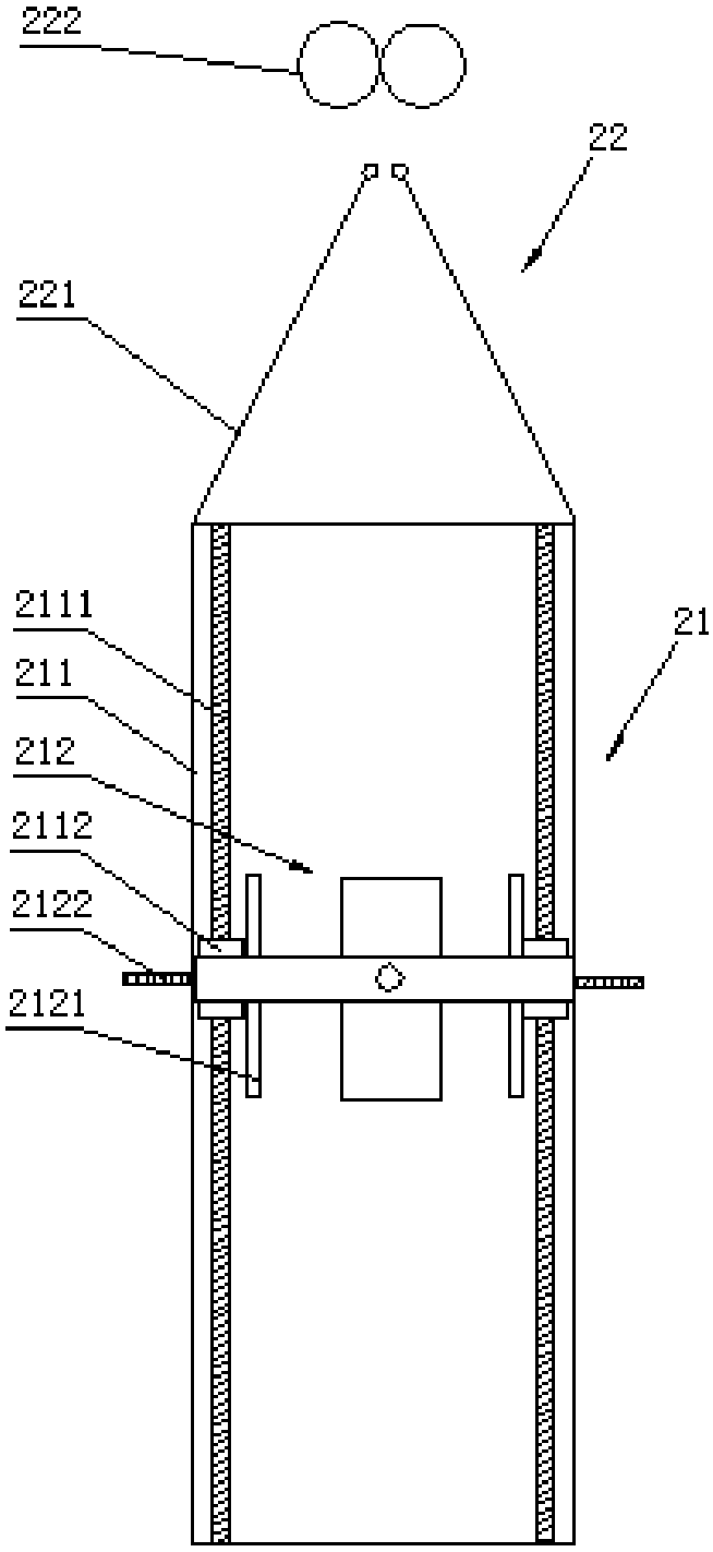
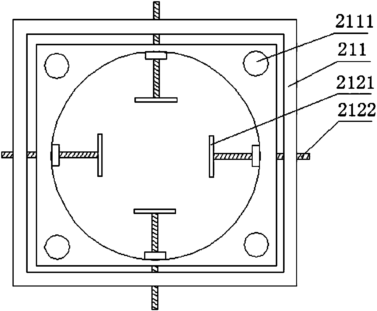
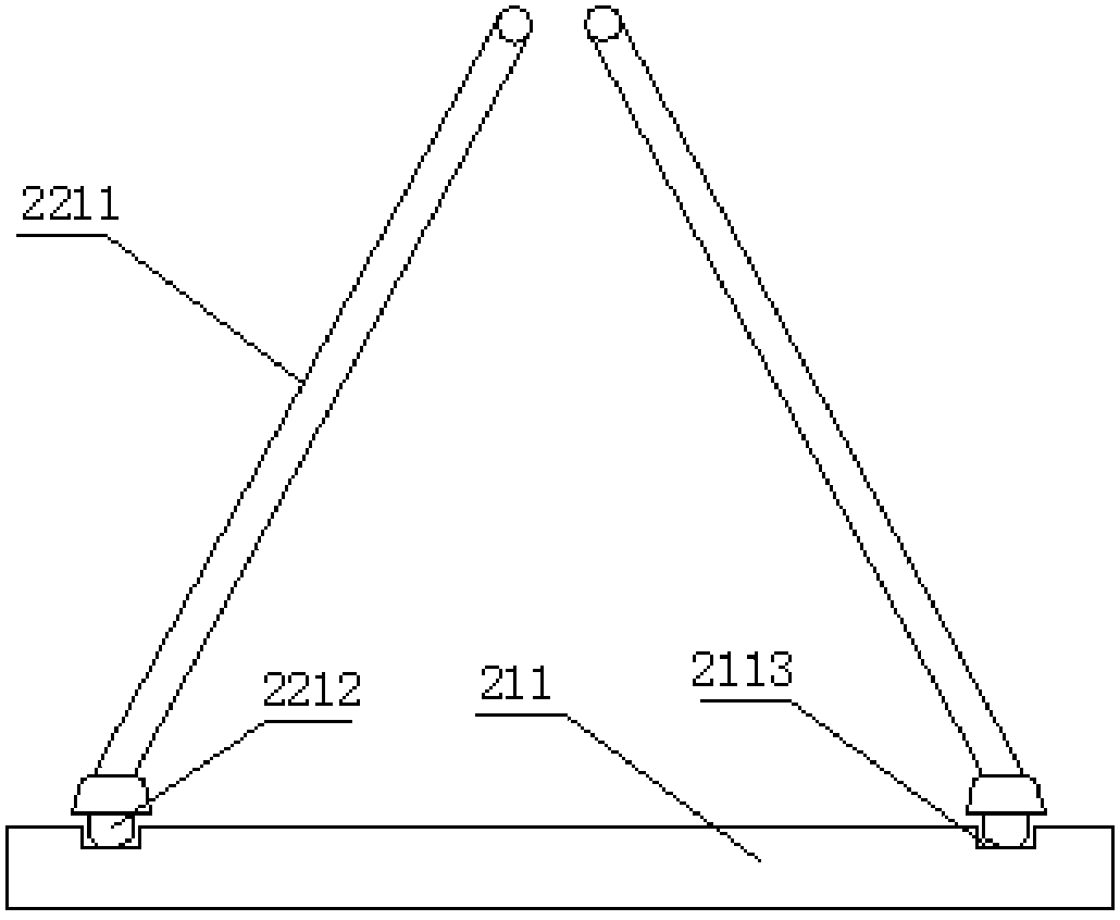
[0037] like figure 1 , 2 , As shown in 3, the traditional bubble stabilization rack does not have the adjustment of height and diameter, and its adaptability is poor. The bubble stabilizing rack 21 provided by the present invention includes a bracket 211; a bubble stabilizing frame 212 is fixed on the inner wall of the bracket 211; a guide column 2111 is arranged on the bracket 211; the bubble stabilizing frame 212 moves up and down along the guide column 2111.

[0038] The bracket 211 provided by the present invention is a rectangular section bracket 211 composed of 4 uprights; a guide post 2111 is respectively fixed on the 4 uprights; the four corners of the foam stabilizing frame 212 have sliding holes; the foam stabilizing frame 212 is sleeved on the Move up and down on the guide post 2111. In order to facilitate the vertical movement and fixing of the bubble stabilizing frame 212, the guide post 2111 provided by the present invention is a screw; the position between the...

Embodiment 2

[0044] like Figure 4 , Figure 5 As shown, the tension roller set includes a plurality of tension rollers 32; the plurality of tension rollers 32 are all fixed on the frame parallel to each other. All be provided with antistatic device 31 on each tension roller 32; Antistatic device 31 is to be provided with a wet cloth strip along the axial direction of tension roller 32; Pass between the rollers 32;

Embodiment 3

[0046] like Image 6 , Figure 7 As shown, the printing assembly includes a version roller 41, a rubber roller 42, and a scraper 43; , and the scraper 43 is inclined downward from the contact end with the version roller 41 towards the other end; the printing assembly also includes an ink absorbing device; the ink absorbing device includes a suction pipe 44; the mouth of the suction pipe 44 is flat; the lower edge of the mouth of the suction pipe 44 is attached to the scraper Plate 43 and is in printing position of version roller 41.

[0047] The printing assembly also includes a primary drying device; the primary drying device has an air supply port 45; the air supply port 45 is above the scraper 43 and blows air to the film printing position; the wind direction of the primary drying device is from the air outlet to the direction of the film. The direction is sloping from bottom to top.

[0048] The printing machine also includes a secondary drying device 46; the secondary ...


PUM


Abstract

The invention provides a novel film blowing machine. The novel film blowing machine comprises a film blowing device and a printing assembly. A bubble stabilizing device capable of moving up and down is arranged over the film blowing device. A bubble stabilizing frame comprises a bracket. A bubble stabilizing framework is fixed to the inner wall of the bracket. The bracket is provided with guide columns. The bubble stabilizing framework moves up and down along the guide columns. The lower ends of two side wings of a propeller strut are fixed to the bracket, capable of moving oppositely and located over the bubble stabilizing framework. The printing assembly is provided with an ink absorbing device. The bubble stabilizing frame capable of moving up and down is arranged, and baffles adjustable in horizontal distance are arranged on the bubble stabilizing frame, so that film bubbles with different heights and diameters are stabilized and limited; the bubble stabilizing frame and the baffles move easily through the guide columns and horizontal screws; and a sucker is fixed to an inclined scraper and assisted by a suction pump, so that scraped printing ink successfully enters the sucker, and pollution to the working environment is avoided.

Description

technical field [0001] The invention relates to the technical field of plastic film production, in particular to a film blowing machine. Background technique [0002] At present, packaging bags are widely used in daily life and work due to their convenience and simplicity in use and carrying. Plastic products include polyethylene plastic products, polypropylene plastic products and polyvinyl chloride plastic products. These plastic products can not only protect products and facilitate transportation, but also promote sales and beautify products. [0003] The plastic film production equipment of prior art is basically blown film, printing, mutually independent machine. In the production process, the process is complicated, and the film roll will be deformed or damaged during the handling process, resulting in unnecessary waste. The obsolescence of equipment functions leads to defects in low production efficiency and poor film quality. Contents of the invention [0004] ...

Claims


Application Information

Patent Timeline
Patent Type & Authority Patents(China)
IPC IPC(8): B29C55/28B41F19/00B41F23/04H05F3/00B65H18/26
CPCB29C55/28B41F19/00B41F23/0466B65H18/26H05F3/00
Inventor 汪俊
Owner ANQING XINSHUN PLASTIC CO LTD
Learn More