
Quench machining tool with rapid mold changing device and thread opening limiting device

A limit device and quenching machine tool technology, applied in the field of quenching machine tools, can solve the problems of excessive changes in the amount of grinding wheel feed, small replacement space, long replacement time, etc., to improve processing efficiency and pass rate, convenient operation and control, and automation high degree of effect

Active Publication Date: 2016-08-31
NINGXIA MACHINERY RES INST
View PDF4 Cites 0 Cited by
  • Summary
  • Abstract
  • Description
  • Claims
  • Application Information

AI Technical Summary

Problems solved by technology

[0004] At present, all railway bearing molding quenching presses used online in China are mainly to control the deformation of the raceway of the jacket workpiece during the quenching process. The tooth mouth refers to the thinner ring part at both ends of the railway bearing jacket, and the deformation of the tooth mouth has never been uniform. A reasonable mechanism is used for effective control. During the quenching process, the workpiece starts to shrink and hold the mold tightly after rapid cooling. Because the thickness of the tooth mouth is thinner, it first shrinks in place, and the workpiece raceway and the middle part are thicker and unsealed, and will continue to shrink inward. During the contraction process of this part, it will cause different degrees of external expansion and deformation of the mouth mouth, resulting in uncontrollable deformation of the mouth mouth
[0005] Since the traditional processing procedure after quenching, that is, the grinding process is a separate process for the raceway and the tooth gap, it can make up for the shortcomings caused by the large deformation of the tooth gap, but due to the need for two clamping and processing, the processing efficiency is low
With the popularization of intelligent manufacturing and the improvement of automation in enterprises, various railway bearing manufacturers use intelligent grinding machines for one-time grinding of the raceway and the tooth gap for the jacket workpiece. If the deformation of the tooth gap is too large and the concentricity with the raceway If the height cannot be matched, it will bring a very big problem to the one-time grinding process, and the following problems will occur: 1. The grinding of the teeth or the raceway is not in place; 2. Due to the large deformation of the teeth, the grinding wheel enters the grinding process Excessive changes in the amount of knife will quickly reduce or damage the service life of the grinding wheel; 3. The grinding amount is uneven and the scrap rate increases, which seriously affects the production efficiency and economic benefits of the enterprise, and there are certain safety hazards
[0007] When replacing the mold, especially the upper mold of the current molding quenching press, since the upper mold is installed in the quenching oil cover, the replacement space is small, and the quenching oil cover needs to be removed for replacement, resulting in long replacement time and high labor intensity. , which directly affects the production efficiency of the enterprise and the physical and mental health of the operating workers

Method used


Image

  • Quench machining tool with rapid mold changing device and thread opening limiting device
  • Quench machining tool with rapid mold changing device and thread opening limiting device
  • Quench machining tool with rapid mold changing device and thread opening limiting device

Examples


Embodiment Construction

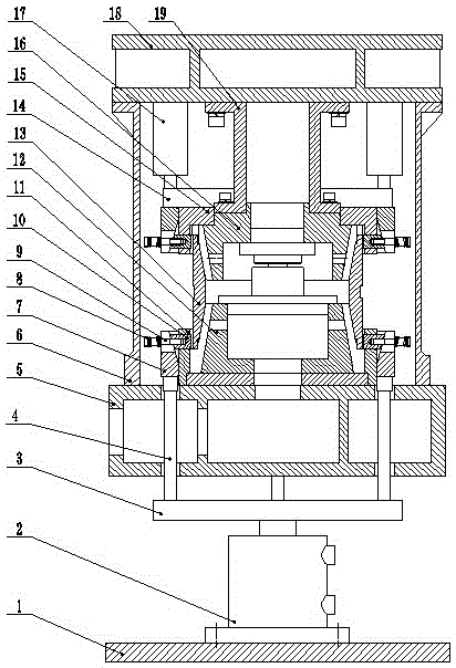
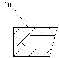
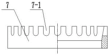
[0031] in the attached Figures 1 to 11 Among them, 1-main base, 2-lower mold cylinder, 3-lower pressure ring, 4-connecting rod, 5-working table, 6-quenching oil cover, 7-ring inner cone, 7-1-"U Shaped groove", 8-spring, 9-screw, 10-limiting block, 11-lower limiting block guide seat, 11-1-limiting block guide hole, 12-lower mold, 13-workpiece, 14-upper pressure ring , 15 - upper limit block guide seat, 16 - upper mold, 17 - upper mold oil cylinder, 18 - moving beam, 19 - upper mold seat, 20 - mold handle, 21 - insert plate, 22 - guide seat, 23 - connecting rod , 24-hinge, 25-connecting plate, 26-mold quick change cylinder, 27-cylinder mounting plate, 28-long groove, 29-ring groove.

[0032] Such as figure 1 As shown, the lower mold cylinder 2 is installed on the main base 1, the lower end of the disc-shaped lower pressure ring 3 is connected with the piston rod in the lower mold cylinder, and the upper plane of the lower pressure ring is fixedly equipped with a connecting ro...


PUM


Abstract

The invention relates to a quenching device, in particular to a quench machining tool with a rapid mold changing device and a thread opening limiting device. The quench machining tool is formed by additionally arranging the thread opening limiting device and replacing a changing device of an upper mold with the rapid changing device adopting a connection rod mechanism driven by an air cylinder for locking and unlocking on the basis of an existing mold pressing quench machining tool, wherein the thread opening limiting device is used for limiting deformation of the thread opening position of a workpiece during quenching. According to the technical scheme, on the one hand, deformation of the thread opening and a roller path of the workpiece is effectively controlled during quenching and reduced, coaxiality is improved, the grinding amount of subsequent machining is effectively reduced, and the machining efficiency and percent of pass of the product are improved; and on the other hand, the changing time of the upper mold of the mold pressing quench machining tool is shortened. By means of the technical scheme, the quench machining tool has the advantages of being reasonable in structure, good in use effect and suitable for improvement of the existing mold pressing quench machining tool.

Description

Technical field [0001] The invention relates to a quenching device, in particular to a quenching machine tool with a mold quick change and a teeth limit device. Background technique [0002] For the sleeve parts that need quenching treatment in the mass processing process, quenching heat treatment is one of the key processes that determine product quality, performance and life. The quenching heat treatment process belongs to thermal processing, and there are many unpredictable factors, such as railway bearings In the manufacturing process of the inner and outer rings, qualified products processed before the process, in the quenching process, after high-temperature heating for a long time, and rapid cooling during quenching, changes in geometric size and shape will inevitably occur. When the deformation is too large , a large number of substandard products will be produced, and the rework rate and scrap rate are high. [0003] At present, for the heat treatment of large quan...

Claims


Application Information

Patent Timeline
Patent Type & Authority Applications(China)
IPC IPC(8): C21D1/673C21D9/40
CPCC21D1/673C21D9/40
Inventor 王国升许军晓李翔
Owner NINGXIA MACHINERY RES INST
Learn More