Vibration centrifugation compound environment simulation test apparatus suitable for component product

An environmental simulation test and centrifugal composite technology, applied in the field of vibration centrifugal composite environmental simulation test device, can solve the problems of long cycle, difficult technical support, high flight test cost, and achieve high excitation frequency, small weight and volume, and vibration excitation. simple effect

Inactive Publication Date: 2016-08-31
GENERAL ENG RES INST CHINA ACAD OF ENG PHYSICS
View PDF11 Cites 4 Cited by
  • Summary
  • Abstract
  • Description
  • Claims
  • Application Information

AI Technical Summary

Problems solved by technology

The first is to conduct actual flight tests. The advantage is that it can truly simulate the complex environment experienced by the flight system. However, flight tests are not only costly and long-term, but also difficult to provide strong technical support in the principle and design stages.
The second way is to conduct mechanical environment simulation tests on the ground, such as vibration tests, centrifugal tests, etc. This kind of single-factor environmental test technology is relatively mature at home and abroad, but multi-factor composite tests are difficult, especially the combination of vibration and overload. Mechanical environment test
However, on the one hand, these inventions cannot simulate the high-frequency vibration of the real flight environment. On the other hand, the volume and complexity of the excitation system are large, which is not conducive to the processing and control accuracy of the control device.

Method used


Image

  • Vibration centrifugation compound environment simulation test apparatus suitable for component product
  • Vibration centrifugation compound environment simulation test apparatus suitable for component product
  • Vibration centrifugation compound environment simulation test apparatus suitable for component product

Examples


Embodiment Construction

[0018] The present invention will be further described below in conjunction with accompanying drawing:

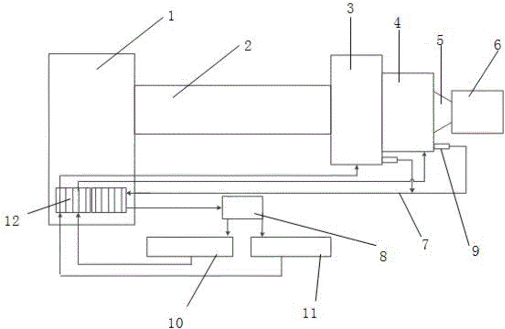
[0019] Such as figure 1 As shown, the present invention includes a centrifuge and a vibration control system 8. The centrifuge is provided with a main shaft 1 and a boom 2, and the centrifuge can output an overload acceleration value.

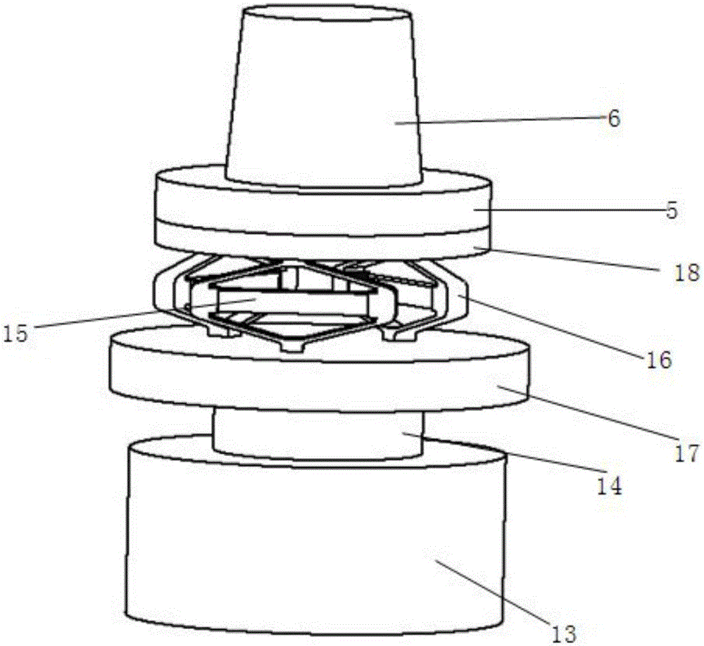
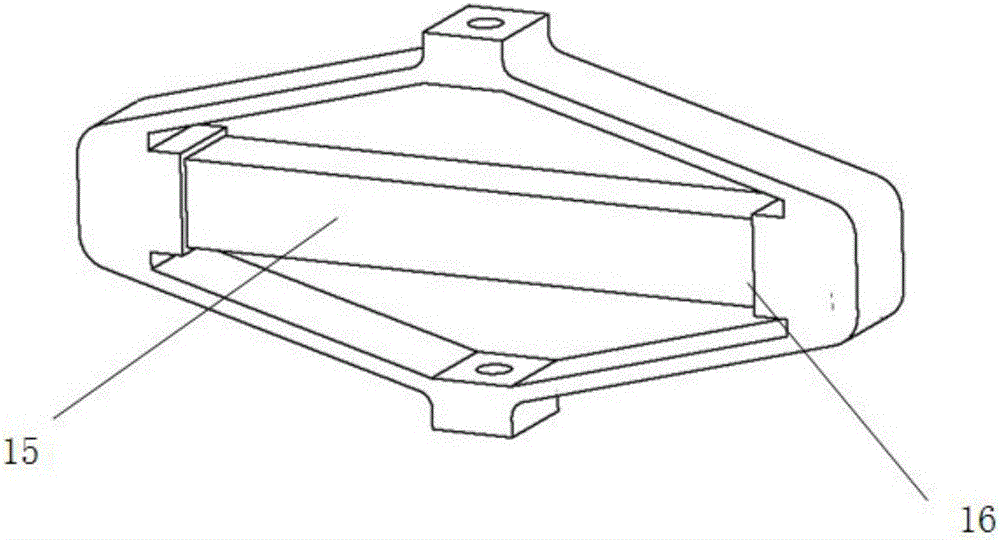
[0020] The end of the boom 2 is provided with a hydraulic excitation system 3, a piezoelectric excitation system 4 and a fixture 5 for fixing the test piece 6. The hydraulic excitation system 3 provides vibration acceleration in the middle and low frequency range, and the piezoelectric excitation system 4 Together with the hydraulic excitation system 3, it forms a broadband vibration system.

[0021] The hydraulic vibration excitation system 3 is fixedly connected with the boom 2, the vibration direction of the hydraulic vibration excitation system 4 is consistent with the axial direction of the boom 2, the piezoelectric vibration excitatio...


PUM


Abstract

The invention discloses a vibration centrifugation compound environment simulation test apparatus suitable for a component product. The apparatus comprises a centrifugal machine and a vibration control system. A large arm tail end of the centrifugal machine is provided with a hydraulic shock excitation system, a piezoelectric shock excitation system and a clamp. The hydraulic shock excitation system is fixedly connected to a large arm. A shock excitation direction of the hydraulic shock excitation system is consistent with a large arm axis direction. The piezoelectric shock excitation system is connected rigidly in series. The clamp is fixedly connected to the piezoelectric shock excitation system. The piezoelectric shock excitation system and the hydraulic shock excitation system are provided with acceleration sensors. A signal output terminal of each acceleration sensor is connected to a vibration signal input terminal of a vibration control system through a collecting ring. The vibration control system is electrically connected to a power amplifier and a hydraulic driving system. The power amplifier is electrically connected to the piezoelectric shock excitation system through the collecting ring. A hydraulic driving system is connected to the hydraulic shock excitation system through the collecting ring. By using the apparatus of the invention, composite output of a vibration accelerated speed and an overload accelerated speed from a low frequency to a high frequency can be completed.

Description

technical field [0001] The invention belongs to the technical field of mechanical environmental tests, and in particular relates to a vibration-centrifugal compound environment simulation test device suitable for component products. Background technique [0002] The complex environment of high-frequency vibration, dynamic overload, temperature and impact experienced by weapons and aerospace systems during flight has complex effects on the structural strength and reliability of products, especially the combination of vibration and overload, which is the most important factor affecting the structure and function of flight products. Two environmental factors are significant. With the rapid development of weapons and aerospace, the assessment of structural strength and functional reliability of mechanisms and electronic equipment in weapons and aerospace systems has become the focus of related industries. [0003] There are two main methods of assessment. The first is to condu...

Claims


Application Information

Patent Timeline
Patent Type & Authority Applications(China)
IPC IPC(8): G01M7/02
CPCG01M7/02G01M7/022
Inventor 凌明祥李思忠刘谦郑星师伟鹏严侠
Owner GENERAL ENG RES INST CHINA ACAD OF ENG PHYSICS
Why Eureka
Try Eureka