Precipitated sludge backflow coagulation aiding and re-nucleation clarifying device

A sludge return and clarification device technology, applied in flocculation/sedimentation water/sewage treatment, water/sludge/sewage treatment, water/sewage treatment, etc. Complicated problems, to achieve stable and efficient treatment effects, to solve the effect of large footprint and compact device structure

Active Publication Date: 2016-09-07
SHAANXI URSTAR ENVIRONMENTAL SCI & TECH
View PDF7 Cites 8 Cited by
  • Summary
  • Abstract
  • Description
  • Claims
  • Application Information

AI Technical Summary

Problems solved by technology

[0006] Invention patent CN 102078708B discloses a solid-liquid separator that relies on hydrocyclone to granulate and grow suspended matter in water to achieve solid-liquid separation. The processing technology of this equipment is too complicated, and it is inconvenient to manufacture and install
This process is aimed at urban water supply treatment. The coagulation tank, filling tank, flocculation tank and high-efficiency sedimentation tank are arranged in series. It requires special fine sand dosing equipment and sand-water separation equipment. The process is long and the cost of equipment is high, and the cost of fine sand raw materials is high.
[0009] Generally speaking, the volume of the coagulation tank and sedimentation tank in the existing clarification devices is often too large, the space utilization rate is not high, the flocs are loose, the design hydraulic retention time is greater than the actual hydraulic retention time, and the effect is poor

Method used


Image

  • Precipitated sludge backflow coagulation aiding and re-nucleation clarifying device
  • Precipitated sludge backflow coagulation aiding and re-nucleation clarifying device

Examples


Embodiment Construction

[0027] The content of the present invention is described below in conjunction with the accompanying drawings. The following description is only exemplary and explanatory, and should not have any limitation on the protection scope of the present invention.

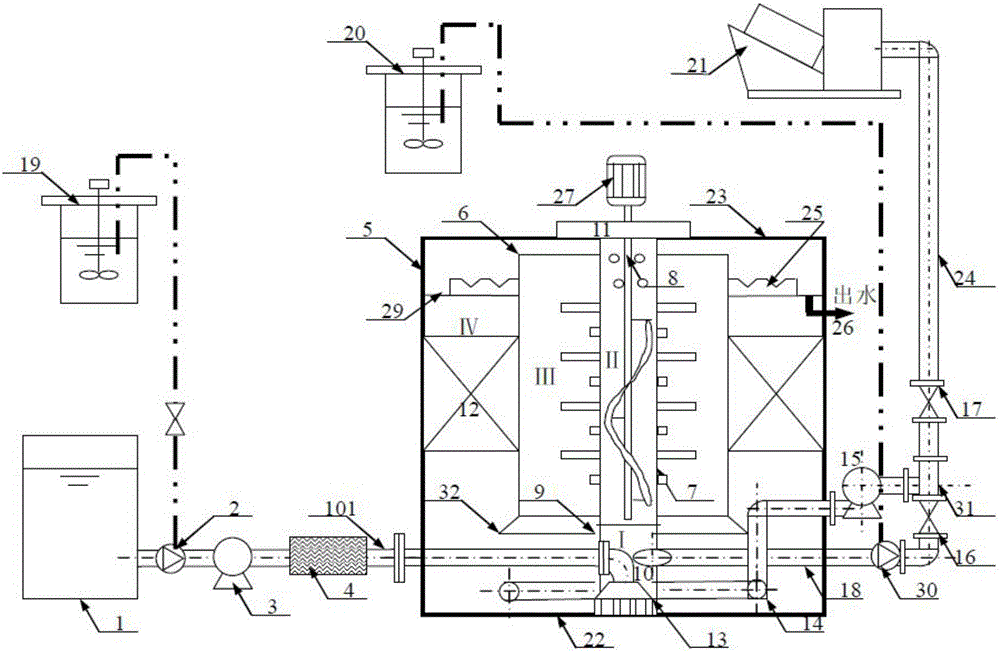
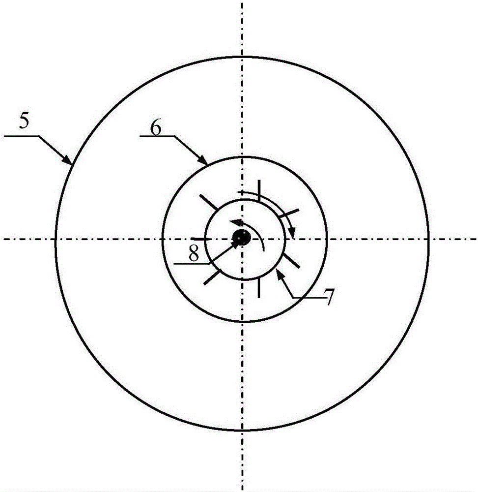
[0028] See figure 1 with figure 2 The device of the present invention includes a water inlet and outlet unit, a medicament dosing and mixing unit, a coagulation sedimentation unit and the like. The effluent in the raw water tank 1 passes through the coagulant dosing port 2, and then sequentially passes through the lift pump 3 and the pipeline mixer 4, and then enters the mixing zone I in the shell through the water inlet 13. The shell consists of a coaxial outer cylinder 5, The middle cylinder 6 and the inner cylinder 7 are composed of three layers of cylinders. The whole shell is cylindrical. The three layers of cylinders divide the space area into four parts, namely, water inlet and return flow sedimentation sludge mixing z...


PUM


Abstract

A precipitated sludge backflow coagulation aiding and re-nucleation clarifying device comprises a water inlet and outlet unit, an agent adding and mixing unit and a coagulation precipitating unit. The coagulation precipitating unit comprises a shell connected with a water outlet part of a raw water tank. The shell is composed of an outer cylinder, a middle cylinder and an inner cylinder which are coaxial, a mixing area, a coagulating area, a flocculating area and a precipitating area are formed in the shell, a sludge outlet pipe is arranged at the bottom of the flocculating area, a water inlet and backflow precipitate sludge mixing area is communicated with a backflow sludge pipe, the sludge outlet pipe and the backflow sludge pipe are communicated with the rest of sludge pipes outside the shell, coagulation granules precipitate in the precipitating area by relaying on the gravity action. Raw water, a coagulating agent, a coagulant aid and backflow sludge are fully mixed in the mixing area. A coagulating reaction occurs with backflow sludge granules as coagulating nucleuses in the coagulating area. Growth and granulation of flocculating constituents are promoted with the re-nucleation action of the backflow sludge granules in the flocculating area. The precipitated sludge backflow coagulation aiding and re-nucleation clarifying device has the advantages that small agent consumption is achieved, the occupied area is small, outlet water quality is good, the backflow concentration of sludge is large, a small backflow amount is achieved, and control is easy.

Description

Technical field [0001] The invention belongs to the technical field of water treatment, and relates to the removal of suspended solids in water supply, domestic sewage and industrial wastewater, and particularly relates to a settling sludge backflow assisting coagulation and nucleation clarification device. Background technique [0002] The clarification process of raw water is a complex physical and chemical process, usually including coagulation, flocculation and sedimentation processes. The coagulation mechanism mainly includes the ZTA potential theory, and the precipitation process is mainly based on the compression precipitation theory. [0003] The coagulation process requires that the hydrolysate of the coagulant rapidly diffuse into the water, and all colloidal particles are destabilized and agglomerated almost at the same instant, so that a good flocculation effect can be obtained. In order to achieve a good flocculation effect, a pipeline mixer is usually used in the tre...

Claims


Application Information

Patent Timeline
Patent Type & Authority Applications(China)
IPC IPC(8): C02F1/52
CPCC02F1/52C02F1/5209C02F2301/046C02F2301/08
Inventor 金鹏康朱秀荣邱壮王晓昌
Owner SHAANXI URSTAR ENVIRONMENTAL SCI & TECH
Why Eureka
Try Eureka