Low-voltage network electric pole

A low-voltage distribution network and pole technology, applied in the field of low-voltage distribution network poles, can solve problems such as poor bending resistance, easy loosening and falling off, and limited strength, so as to achieve increased tensile strength, ensure safety, and reduce effect of weight

Inactive Publication Date: 2016-09-07
STATE GRID SHANDONG ELECTRIC POWER CO BINZHOU CITY BINCHENG DISTRICT POWER SUPPLY CO
View PDF10 Cites 4 Cited by
  • Summary
  • Abstract
  • Description
  • Claims
  • Application Information

AI Technical Summary

Problems solved by technology

However, most of the existing electric poles are designed as simple hollow cement tubes, which are heavy, limited in strength, poor in bending resistance, and easily damaged by external forces and collapsed.
In addition, the poles are also fixed on the poles by screws, which are easy to loosen and fall off after a long time, causing power failure accidents

Method used


Image

  • Low-voltage network electric pole

Examples


Embodiment 1

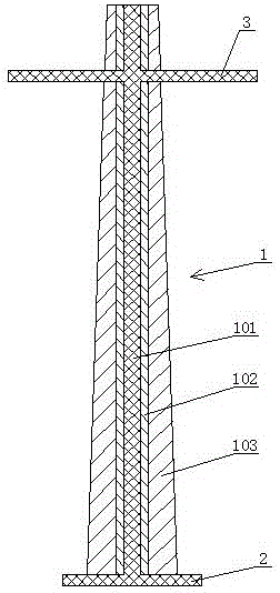
[0023] As shown in the figure, the present invention includes a rod body 1. The rod body 1 includes a supporting stem 101. The outer surface of the supporting stem 101 is provided with a cloth-impregnated resin layer 102. The outer surface of the cloth-impregnated resin layer 102 is provided with a protective layer 103. The resin layer 102 is fiberglass cloth or carbon fiber cloth or glass fiber cloth or non-woven fabric impregnated with resin, and the cloth impregnated with resin layer 102 is tightly wound on the outer surface of the support core 101 after melting. The bottom of the rod body 1 is provided with a base 2 fixedly connected to the supporting stem 101 , and the upper part of the rod body 1 is provided with a wire rack rod 3 fixedly connected to the supporting stem 101 , and the wire rack rod 3 is perpendicular to the supporting stem 101 . The upper and lower ends of the supporting stem 101 are provided with terminals (not shown in the figure) for connecting to ligh...

Embodiment 2

[0034] The difference between this embodiment and Embodiment 1 is that the supporting core 101 column includes the following raw materials in parts by weight: 40 parts of Ti, 40 parts of Al, 5 parts of Cr, 1 part of Mn, 8 parts of tetraacicular zinc oxide whiskers, mixed rare earth 1 serving. The mixed rare earth is composed of yttrium, berkelium and lanthanum, and the mass ratio of the three is 1: (0.20-0.22): (0.30-0.32).

Embodiment 3

[0036] The difference between this embodiment and Embodiment 1 is that the supporting stem 101 includes the following raw materials in parts by weight: 60 parts of Ti, 60 parts of Al, 10 parts of Cr, 3 parts of Mn, 10 parts of tetraacicular zinc oxide whiskers, mixed rare earth 4 parts. The mixed rare earth is composed of yttrium, berkelium and lanthanum, and the mass ratio of the three is 1: (0.20-0.22): (0.30-0.32).


PUM


Abstract

The invention relates to a low-voltage network electric pole. The low-voltage network electric pole comprises a pole body. The pole body comprises a supporting core column, a resin-soaking cloth layer is arranged on the outer surface of the supporting core column, a protective layer is arranged on the outer surface of the resin-soaking cloth layer, and the resin-soaking cloth layer is fiber reinforced polymer cloth or carbon fiber cloth or glass fiber cloth or non-woven cloth soaked with resin and is tightly wound on the outer surface of the supporting core column after being molten. A base fixedly connected with the supporting core column is arranged at the bottom of the pole body, and a wire frame pole fixedly connected with the supporting core column is arranged on the upper portion of the pole body. The supporting core column comprises the following raw materials of, by weight, 40-60 parts of Ti, 40-60 parts of Al, 5-10 parts of Cr, 1-3 parts of Mn, 8-10 parts of tetrapod-shaped ZnO whiskers and 1-4 parts of mixed rare earth, the length of the tetrapod-shaped ZnO whiskers is 10-12 micrometers, and the root diameter of the tetrapod-shaped ZnO whiskers is 1-1.5 micrometers. The low-voltage network electric pole is reasonable in structural design, high in strength, good in anti-bending performance and light in weight. A wire erecting rod is fixedly connected with the supporting core column, and the reliability of connection is guaranteed.

Description

technical field [0001] The invention relates to a pole of a low-voltage distribution network. Background technique [0002] The low-voltage distribution network is composed of overhead lines, cables, poles, distribution transformers, isolating switches, reactive power compensators and ancillary facilities, etc., and plays an important role in distributing electric energy in the power network. The pole is an important part of the transmission line equipment of the low-voltage distribution network, and it undertakes the important task of erecting the transmission line. However, most of the existing electric poles are designed as simple hollow cement tubes, which are heavy, have limited strength, poor bending resistance, and are easily damaged by external forces and collapse. In addition, the wire poles are also fixed on the poles by screws, which are easy to loosen and fall off after a long time, causing power failure accidents. Contents of the invention [0003] The inven...

Claims


Application Information

Patent Timeline
Patent Type & Authority Applications(China)
IPC IPC(8): E04H12/02C22C49/12C22C49/14C22C101/02
CPCE04H12/02C22C49/12C22C49/14
Inventor 张洁刘睿民王红泰陈磊吕洪光范勇董硕白红岩魏承诚刘斌王鹏飞
Owner STATE GRID SHANDONG ELECTRIC POWER CO BINZHOU CITY BINCHENG DISTRICT POWER SUPPLY CO
Why Eureka
Try Eureka