Reciprocating grate biomass boiler furnace

A biomass boiler and reciprocating grate technology, applied in the boiler field, can solve the problems of increasing fuel chemical incomplete combustion loss, slow burning speed of coke particles, long drying time, etc., to solve drying problems and oxygen supply problems, and promote The effect of further complete combustion and prolonging the residence time

Active Publication Date: 2018-03-23
董磊
View PDF7 Cites 0 Cited by
  • Summary
  • Abstract
  • Description
  • Claims
  • Application Information

AI Technical Summary

Problems solved by technology

[0005] (1) The moisture content of biomass is high, and combustion requires a higher drying temperature and a longer drying time;
[0006] (2) The density of biomass fuel is small, the structure is relatively loose, the area facing the wind is large, it is easy to be blown up, and the proportion of suspended combustion is large, which requires a large amount of oxygen supply in the furnace space;
[0008] (4) Due to the high volatile content of biomass, the ignition temperature of fuel is relatively low. Generally, at a temperature of 250°C to 350°C, a large amount of volatile matter will precipitate and start to burn violently. At this time, if the air supply is insufficient, the fuel will increase. chemical incomplete combustion losses;
[0009] (5) After the volatile matter is precipitated and burnt out, affected by the ash wrapping and the difficulty of air infiltration, the coke particles burn slowly and are difficult to burn out. If appropriate and necessary measures are not taken, more residual carbon will remain in the ash , increasing mechanical incomplete combustion losses

Method used


Image

  • Reciprocating grate biomass boiler furnace

Examples


Embodiment Construction

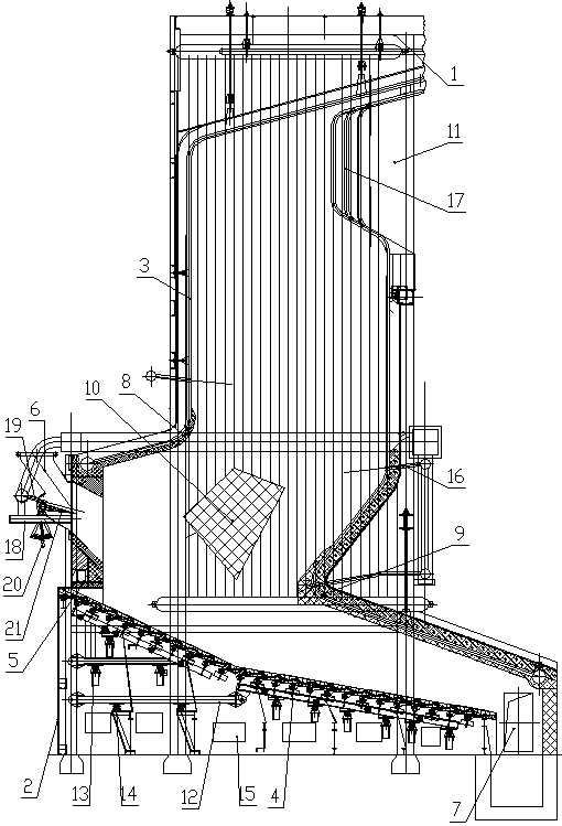
[0026] Such as figure 1 As shown, the reciprocating grate biomass boiler furnace of the present invention includes a bracket 1 and a support structure 2. A full-membrane water-cooled furnace wall 3 welded by pipes side by side is hung on the bracket 1, and small scales are arranged on the support structure 2. Fire grate 4, a sealed expansion structure 5 is provided between the lower end of the full-membrane water-cooled furnace wall 3 and the small scale fire grate 4, and a feed port 6 is provided on the front side of the lower part of the full-film water-cooled furnace wall 3, and the full-film water-cooled furnace wall A slag outlet 7 is provided between the rear side of the lower part and the small scale grate 4, and a front arch 8 and a rear arch 9 are respectively provided on the front side and the rear side of the lower part of the full-film water-cooled furnace wall 3. The small scale grate 4A two-stage or three-stage structure is adopted, and the small scale grate 4 of...


PUM


Abstract

A reciprocating grate biomass boiler hearth comprises a full-film type water cooling boiler wall and a small scale grate, wherein the full-film type water cooling boiler wall is formed by welding pipelines side by side. A feeding port is formed in the front side of the lower portion of the full-film type water cooling boiler wall. A slag outlet is formed between the rear side of the lower portion of the full-film type water cooling boiler wall and the small scale grate. A two-section or three-section type structure is adopted in the small scale grate. Each section of the small scale grate is obliquely arranged in the manner that the front portion is high, and the rear portion is low. A heat insulation stable combustion device is arranged between a front arch and a rear arch in the full-film type water cooling boiler wall and made of a fireproof heat accumulation material. A smoke outlet is formed in the rear side of the upper portion of the full-film type water cooling boiler wall. The reciprocating grate biomass boiler hearth solves the problem of biomass fuel drying and the problem of oxygen supplying, the combustion staying time of biomass in a boiler is prolonged, the temperature of the interior of the boiler during fuel combustion is stabilized, the mixing of high-temperature smoke, air and biomass material particles is enhanced through a water cooling wind power composite arch, combustible gas and solid particles are promoted to be further fully combusted, and the combustion efficiency of the boiler is improved.

Description

technical field [0001] The invention belongs to the technical field of boilers, in particular to a reciprocating grate biomass boiler furnace. Background technique [0002] With the rapid growth of the world's energy demand, the conventional energy represented by coal, oil, and natural gas will eventually be exhausted, and the large-scale use of these fossil fuels will lead to a series of serious environmental pollution problems. Therefore, vigorously improving energy utilization efficiency, developing low-pollution, renewable new energy sources with high technology, and gradually replacing non-renewable energy sources such as oil, coal, and natural gas are important ways to solve energy crisis and environmental problems. Among the many renewable energy sources, biomass energy has great development potential because of its abundant resource reserves, clean, convenient and renewable characteristics. [0003] Biomass energy refers to the energy stored in biomass by green plan...

Claims


Application Information

Patent Timeline
Patent Type & Authority Patents(China)
IPC IPC(8): F23B30/10F23M5/06F23M5/08F23J15/00
CPCF23B7/002F23B30/10F23J15/006F23M5/06F23M5/08F23M5/085
Inventor 范高峰董磊马慧敏马震宋廷齐
Owner 董磊
Why Eureka
Try Eureka