Convective dust removal device and smoke-free waste incineration system

A technology of dust removal device and garbage incineration, which is applied in the direction of combination device, incinerator, combustion method, etc., and can solve the problems of soil compaction, groundwater quality deterioration, low nutrient content, and insufficient garbage incineration, etc.

Active Publication Date: 2016-09-07
陈仕敏
View PDF5 Cites 0 Cited by
  • Summary
  • Abstract
  • Description
  • Claims
  • Application Information

AI Technical Summary

Problems solved by technology

It not only solves the way out of garbage, but also achieves the purpose of recycling. However, the amount of domestic garbage compost is large and the nutrient content is low. Long-term use may easily cause soil compaction and groundwater quality deterioration
The incineration method is a method of placing garbage in a high-temperature furnace to fully oxidize the combustible components. At present, there are mainly reburning, rotating furnace, pyrolysis, etc., and the treatment effect is good, but they all have large investment and waste. The combustion volume is small, the garbage is not fully burned, and the smoke and dust treatment is difficult to meet the standards, etc.

Method used


Image

  • Convective dust removal device and smoke-free waste incineration system
  • Convective dust removal device and smoke-free waste incineration system
  • Convective dust removal device and smoke-free waste incineration system

Examples


Embodiment Construction

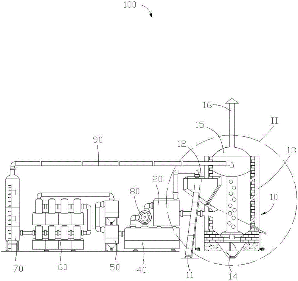
[0022] See figure 1 In an embodiment of the present invention, a smoke-free garbage incineration system 100 includes an incinerator 10, a dust interception box 20, a tar treatment chamber 40, a cyclone settling tank 50, a counter-current dust removal device 60 and a smoke Gas purification tower 70. The incinerator 10 communicates with the dust interception box 20, the tar processing chamber 40 communicates with the dust interception box 20 through a suction structure 80, the cyclone settling tank 50 communicates with the convection dust removal device 60, and the convection The dust removal device 60 is connected to the flue gas purification tower 70, and the flue gas purification tower 70 is connected to the incinerator 10 through a smoke exhaust pipe 90. In the embodiment of the present invention, the suction structure 80 is a high-pressure fan.

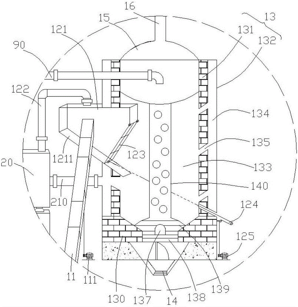
[0023] Please refer to figure 2 The incinerator 10 includes a feeding device 11, a drying chamber 12, a furnace body 13, a slag di...


PUM


Abstract

The invention provides a convective dust removal device which comprises a plurality of water tanks, a smoke inlet condensation cylinder, a plurality of middle condensation cylinders, a smoke outlet condensation cylinder and a plurality of communicating pipes, wherein the number of the smoke inlet condensation cylinder, the middle condensation cylinders and the smoke outlet condensation cylinder is equal to that of the water tanks; the smoke inlet condensation cylinder, the middle condensation cylinders and the smoke outlet condensation cylinder are mounted on the water tanks respectively, communicate with the corresponding water tanks respectively and communicate with one another through the communicating pipes in sequence; one end of the communicating pipe between the smoke inlet condensation cylinder and the middle condensation cylinder adjacent to the smoke inlet condensation cylinder or between every two adjacent condensation cylinders or between the middle condensation cylinder adjacent to the smoke outlet condensation cylinder and the smoke outlet condensation cylinder is connected with the smoke inlet condensation cylinder or one middle condensation cylinder, and the other end of the communicating pipe extends into another middle condensation cylinder or the smoke outlet condensation cylinder, so that smoke is jet into the middle condensation cylinders or the smoke outlet condensation cylinder; the center axis of the end part, extending into one middle condensation cylinder or the smoke outlet condensation cylinder, of each communicating pipe is perpendicular to the horizontal plane of the corresponding water tank; the smoke inlet condensation cylinder communicates with a smoke exhaust pipe which is vertically inserted into the smoke inlet condensation cylinder and is perpendicular to the horizontal plane of the corresponding water tank; and the smoke outlet condensation cylinder is connected with another smoke exhaust pipe.

Description

【Technical Field】 [0001] The invention relates to a garbage incineration system, in particular to a convection dust removal device in the garbage incineration system. 【Background technique】 [0002] With the improvement of living standards, a large amount of domestic garbage will follow. At present, the main methods of garbage disposal are sanitary landfill, high-temperature composting and incineration. The sanitary landfill method has a large waste disposal capacity and simple operation, but the investment is large and the leachate produced by the waste is difficult to deal with. The damage of the anti-seepage membrane or the overturning of the landfill leachate can easily cause a large amount of waste water to infiltrate the ground from the surface, which will affect the surrounding environment. And groundwater sources cause serious pollution. The high-temperature composting method makes the garbage become hygienic and odorless humus after composting. It not only solves the w...

Claims


Application Information

Patent Timeline
Patent Type & Authority Applications(China)
IPC IPC(8): F23G5/44F23J15/04B01D50/00
CPCF23G5/44F23J15/04B01D2258/0291B01D50/10B01D50/40
Inventor 陈仕敏
Owner 陈仕敏
Why Eureka
Try Eureka