Integrated optical circuit structure fiber-optic gyroscope and work method thereof

A fiber optic gyroscope and integrated optical circuit technology, applied in Sagnac effect gyroscope and other directions, can solve the problems of low coupling efficiency of optoelectronic devices, high power consumption of fiber optic gyroscope system, low precision of fiber optic gyroscope system, etc., and it is easy to achieve parameters such as structure. Adjusting, reducing the difficulty of the assembly process, and the effect of low cost

Active Publication Date: 2016-09-07
XIAN SINO HUAXIN MEASUREMENT & CONTROL
View PDF6 Cites 9 Cited by
  • Summary
  • Abstract
  • Description
  • Claims
  • Application Information

AI Technical Summary

Problems solved by technology

However, the optical path of this classic solution is complicated to manufacture, the processing technology is immature, high-cost special equipment is required, and three optical devices need to be independently produced to realize the basic functions, resulting in a relatively large volume of the optical path system, and the polarizer produced by the existing process is extinction The ratio is only 26dB, which leads to low accuracy of the fiber optic gyroscope system, and the coupling efficiency of the online coupled optoelectronic device is low. In order to improve the signal-to-noise ratio of the system, it is necessary to increase the driving current of the light source, which directly leads to excessive power consumption of the fiber optic gyroscope system, which limits its performance. Industry application

Method used


Image

  • Integrated optical circuit structure fiber-optic gyroscope and work method thereof
  • Integrated optical circuit structure fiber-optic gyroscope and work method thereof

Examples


Embodiment Construction

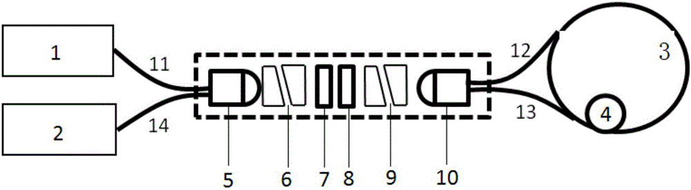
[0032] Below in conjunction with accompanying drawing, the present invention is described in further detail:

[0033] see figure 2 , a fiber optic gyroscope with an integrated optical path structure, including an SLED light source 1, the light source 1 adopts a coaxial package or a butterfly package, the SLED light source 1 is connected to a first lens 5 through a first optical fiber 11, and the rear side of the first lens 5 is sequentially provided with The first polarization beam splitter 6, the Faraday rotator 7, the polarizer 8, the second polarization beam splitter 9 and the second lens 10, and the first lens 5, the first polarization beam splitter 6, the Faraday rotator 7, the polarizer 8, The second polarization beam splitter 9 and the second lens 10 are combined together by packaging, the angle between the polarization direction of the polarizer 8 and the polarization direction of the light passing through the first polarization beam splitter 6 is 45 degrees, and the ...


PUM


Abstract

The invention discloses an integrated optical circuit structure fiber-optic gyroscope and a work method thereof. The integrated optical circuit structure fiber-optic gyroscope comprises a light source. The light source is connected to a first lens through a first optical fiber. The rear side of the first lens is orderly provided with a first polarizing beam splitter, a Faraday rotating plate, a polarizing film, a second polarizing beam splitter and a second lens. The integrated optical circuit structure fiber-optic gyroscope also comprises an optical fiber ring and a phase modulator connected to the optical fiber ring. The optical fiber ring is connected to the second lens through a second optical fiber and a third optical fiber. Each one of the first polarizing beam splitter and the second polarizing beam splitter comprises two optical axis orthogonal homotaxial birefringent crystals. The integrated optical circuit structure fiber-optic gyroscope also comprises a detector. The detector is connected to the first lens through a forth optical fiber. The integrated optical circuit structure fiber-optic gyroscope is free of a thin special optical fiber and a high-precision optical device online production platform, greatly reduces product assembling process difficulty, guarantees a product precision, improves product reliability and lays a foundation for fiber-optic gyroscope market popularity.

Description

technical field [0001] The invention relates to the technical field of optical fiber sensing, in particular to an optical fiber gyroscope with an integrated optical path structure and a working method thereof. Background technique [0002] The fiber optic gyro has a small size, light weight, simple structure and excellent performance and has a broad market potential in the field of inertial measurement. [0003] The current classic fiber optic gyroscope technology solutions such as figure 1 As shown, its working process is: after the light emitted by the light source SLD is split by the light source coupler, half of the light enters the polarizer, and produces single-mode and single-polarized light. The polarized light enters the fiber ring coupler, is divided into two beams of light clockwise and counterclockwise, satisfying the coherence condition, and propagates in the fiber ring. When the optical fiber rotates around its central axis, the Sagnac effect occurs, so that ...

Claims


Application Information

Patent Timeline
Patent Type & Authority Applications(China)
IPC IPC(8): G01C19/72
CPCG01C19/72
Inventor 王辉毛亚敏
Owner XIAN SINO HUAXIN MEASUREMENT & CONTROL
Why Eureka
Try Eureka