
A Temperature Compensation Circuit for Crystal Oscillator

A technology of temperature compensation circuit and crystal oscillator, applied in the direction of electrical components, impedance network, etc., can solve the problems of complex circuit structure, difficulty in integration and miniaturization, and high cost of temperature compensation network

Active Publication Date: 2018-07-27
UNIV OF ELECTRONICS SCI & TECH OF CHINA
View PDF5 Cites 0 Cited by
  • Summary
  • Abstract
  • Description
  • Claims
  • Application Information

AI Technical Summary

Problems solved by technology

[0017] Aiming at the shortcomings of the existing crystal oscillator temperature compensation network, such as high cost, complex circuit structure, and difficulty in integration and miniaturization, the present invention provides a temperature compensation circuit for crystal oscillators. The temperature compensation circuit is based on the temperature of different crystals. Characteristics, generating a reference voltage with adjustable size and temperature coefficient that is a cubic function of temperature. The reference voltage changes the load capacitance of the crystal by controlling the capacitance of the varactor diode, thereby compensating the offset of the crystal oscillation frequency due to temperature changes. Improve frequency stability

Method used


Image

  • A Temperature Compensation Circuit for Crystal Oscillator
  • A Temperature Compensation Circuit for Crystal Oscillator
  • A Temperature Compensation Circuit for Crystal Oscillator

Examples


Embodiment Construction

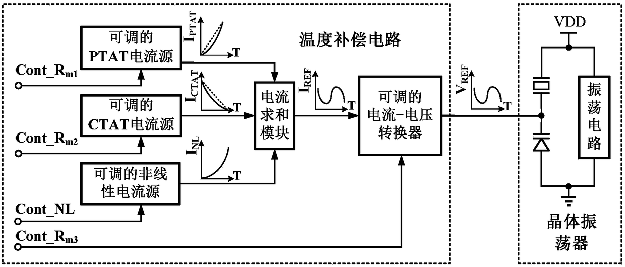
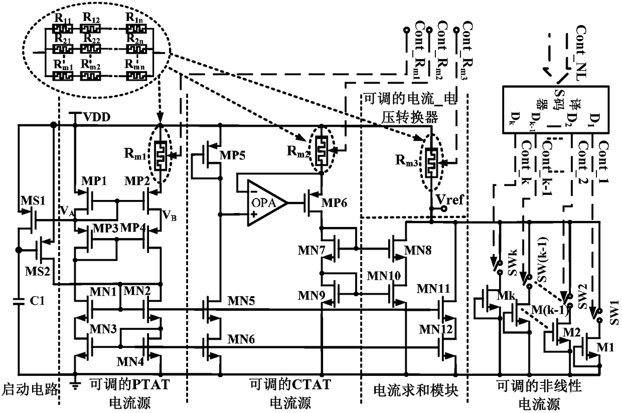
[0072] Combine below figure 1 and figure 2 A specific embodiment of a temperature compensation circuit for a crystal oscillator of the present invention is given. It should be noted that this embodiment is only for explaining the present invention, but not limiting the present invention.

[0073] figure 1 It is a functional block diagram of a temperature compensation circuit for a crystal oscillator provided in this embodiment, and the temperature compensation circuit operates when the control signal Cont_R m1 , Cont_R m2 , Cont_R m3 Under the action of Cont_NL, the reference voltage V with adjustable size, primary coefficient, quadratic coefficient and cubic coefficient can be generated ref , the voltage controls the capacitance of the varactor diode in the crystal oscillator, thereby compensating the deviation of the oscillation frequency of the crystal oscillator due to temperature changes.

[0074] figure 2 It is a circuit structure of a temperature compensation c...


PUM


Abstract

The invention belongs to the field of integrated circuits, in particular to a temperature compensation circuit for a crystal oscillator. The temperature compensation circuit of the present invention generates a reference voltage Vref that is a cubic function of the temperature, and under the action of the control signals Cont_Rm1, Cont_Rm2, Cont_Rm3 and Cont_NL, it realizes the magnitude of the output reference voltage, the coefficient of the first term, the coefficient of the second term, and the third term. Coefficient control, so as to change the temperature coefficient of the reference voltage and the zero temperature coefficient point according to the temperature-frequency characteristics of different crystals. The reference voltage controls the capacitance of the varactor diode, thereby accurately compensating the deviation of the oscillation frequency of the crystal oscillator due to temperature changes, and improving the temperature stability of the frequency. The invention realizes the generation of reference voltages with different temperature coefficients and zero temperature coefficient points for crystals with different temperature characteristics, high flexibility, high compensation precision, simple circuit structure, low cost, and easy miniaturization and integration.

Description

technical field [0001] The invention belongs to the field of integrated circuits, and relates to a temperature compensation circuit of a crystal oscillator, in particular to a reference voltage generation circuit with a cubic function to temperature. Background technique [0002] As a stable frequency source, crystal oscillators are widely used in portable electronic equipment and wireless communication technology, and the stability of their frequency to temperature changes is one of the important indicators to measure the performance of crystal oscillators. The temperature compensated crystal oscillator reduces the offset of the crystal oscillator output frequency due to temperature changes through a temperature compensation network, thereby improving frequency stability. [0003] For the AT-cut quartz resonator commonly used in crystal oscillators, the relationship between its resonant frequency and temperature is described by a cubic curve, specifically: [0004] f(T)=f ...

Claims


Application Information

Patent Timeline
Patent Type & Authority Patents(China)
IPC IPC(8): H03H9/02H03H9/19
CPCH03H9/02834H03H9/19
Inventor 刘洋高宝玲徐振涛郭睿王俊杰雷旭于奇
Owner UNIV OF ELECTRONICS SCI & TECH OF CHINA
Learn More