Wind power and photovoltaic microgrid water pumping and energy storing power generation system

A pumped storage and power generation system technology, applied in photovoltaic power generation, wind power generation, photovoltaic power stations, etc., can solve problems such as low efficiency of power generation utilization, achieve the effect of reducing impact and meeting the overall planning and scheduling

Active Publication Date: 2016-09-14
CHANGAN UNIV
8 Cites 12 Cited by

AI-Extracted Technical Summary

Problems solved by technology

[0004] In view of the intermittent characteristics of wind power and the low efficiency of photovoltaic power generation caused by natural factors, the purpose of the present invention is to provide a wind power photovoltaic micro-grid pumped storage power generation system, which can i...

Method used

Energy storage accumulator group 7 is connected with micro-grid direct-current bus by DC-DC controller, when wind power generation sub-system and photovoltaic power generation sub-system output are almo...

Abstract

The invention discloses a wind power and photovoltaic microgrid water pumping and energy storing power generation system. The system comprises a microgrid direct-current bus, an alternating-current bus, a system controller, a photovoltaic power generation subsystem, a DC-DC controller, a capacitor switch set, a super-capacitor set, an energy-storing battery set, a two-way DC-DC controller, a wind power generation subsystem, an AC-DC controller, a DC-AC controller, a water pump switch set, a water pump unit, a selector switch set, a reversible water turbine set, a thrown-in switch set, a power generator set, a water turbine set, a booster station and a large power grid. The wind power generation subsystem and the photovoltaic power generation subsystem can be subjected to running control at maximum power, maximum energy acquisition is guaranteed, system power balance and electric energy quality are not considered, the thrown-in set number of the super-capacitor set is controlled, smoothing is performed on the voltage of the microgrid direct-current bus, and the bus voltage is kept stable. The electric energy quality problem caused by wind power and photovoltaics can be neglected, the power generation utilizing rate of renewable energy is increased, and reliable, controllable and stable electric energy is provided for the large power grid.

Application Domain

Technology Topic

Image

  • Wind power and photovoltaic microgrid water pumping and energy storing power generation system

Examples

  • Experimental program(1)

Example Embodiment

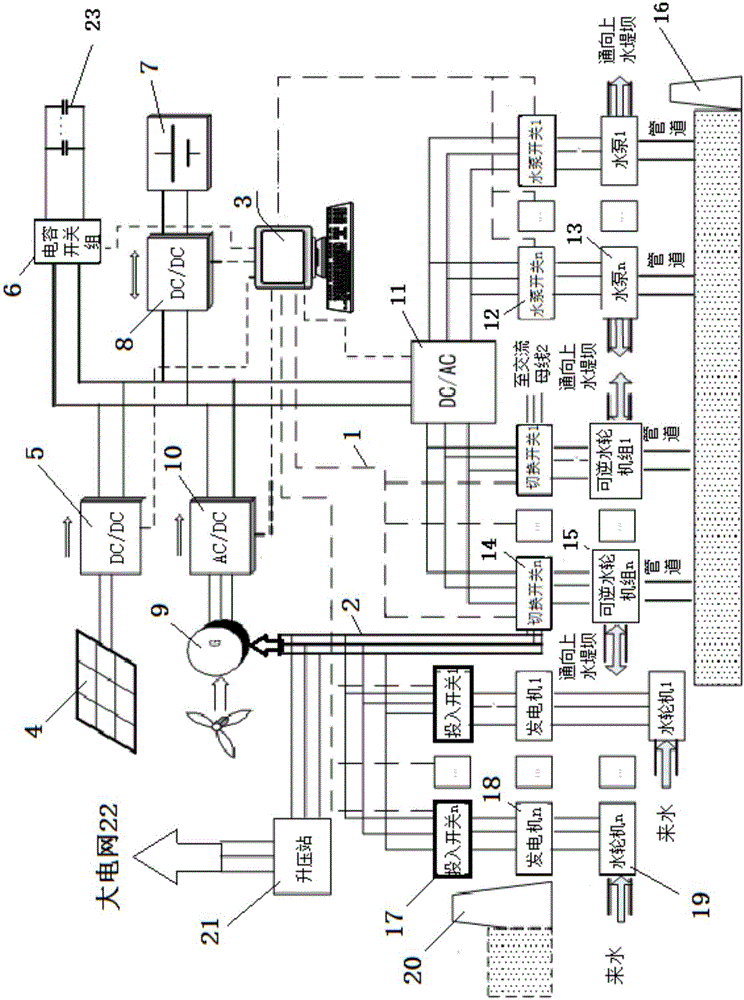
[0027] The key point of the design idea of ​​the present invention is to use wind power photovoltaic electric energy for pumped storage. The pumped storage system contains three types of units: ordinary water pump units, reversible water turbine units and ordinary hydroelectric generating units. The units need system controller intelligence Interpret all information of the system to start and stop.
[0028] See attached figure 1 As shown, this embodiment provides a wind power photovoltaic microgrid pumped-storage power generation system. The system includes microgrid DC bus 1, AC bus 2, system controller 3, photovoltaic power generation subsystem 4, and DC-DC controller 5. Capacitor switch group 6, super capacitor group 23, energy storage battery group 7, two-way DC-DC controller 8, wind power generation subsystem 9, AC-DC controller 10, DC-AC controller 11, water pump switch group 12 , Water pump unit 13, transfer switch unit 14, reversible water turbine unit 15, input switch unit 17, generator unit 18, ordinary water turbine unit 19, booster station 21 and large power grid 22, of which:
[0029] The photovoltaic power generation subsystem 4 and the wind power generation subsystem 9 are connected to the microgrid DC bus 1 through the DC-DC controller 5 and the AC-DC controller 10 respectively; the energy storage battery pack 7 is also connected to the microgrid through the bidirectional DC-DC controller 8 On the micro-grid DC bus 1; the micro-grid DC bus 1 is also connected to the super capacitor group 23 through the capacitor switch group 6;
[0030] The microgrid DC bus 1 is also connected to the DC-AC controller 11. The DC-AC controller 11 is connected to the water pump unit 13 and the reversible water turbine unit 15 through the water pump switch group 12 and the switch group 14 respectively; the water pump unit 13 and the reversible water turbine unit 15 are respectively Connect to the water of the lower dyke 16 through the pipeline;
[0031] The AC bus 2 is connected to the large power grid 22 through the booster station 21, and the AC bus 2 is connected in series to the generator set 18 and the ordinary water turbine unit 19 through the input switch group 17; the AC bus 2 is also connected to the switch group 14;
[0032] The system controller 3 is respectively connected to the DC-DC controller 5, the capacitor switch group 6, the AC-DC controller 10, the two-way DC-DC controller 8, the DC-AC controller 11, the input switch group 17, the water pump switch group 12 and Switch group 14.
[0033] In this embodiment, the photovoltaic power generation subsystem 4 selects a photovoltaic array group.
[0034] The water pumps in the water pump unit 13 are all three-phase AC water pumps.
[0035] In this embodiment, the capacitor switch group 6, the super capacitor group 23, the energy storage battery group 7, the water pump switch group 12, the water pump unit 13, the switch group 14, the reversible water turbine unit 15, the input switch group 17, and the generator unit 18 , Ordinary water turbine unit 19, where "group" means that it contains several identical components. For example, the capacitor switch group 6 includes several capacitor switches, and the ordinary water turbine unit 19 includes several turbines. The figure uses ". .." mark indicates.
[0036] After the wind speed reaches the start-up wind speed, the wind power generation subsystem 9 starts and generates alternating current, which is connected to the microgrid DC bus 1 through the AC-DC controller 10, and the photovoltaic power generation subsystem 4 is connected to the microgrid DC bus 1 through the DC-DC controller 5 Connected to jointly output electric energy to the super capacitor group 23, the energy storage battery group 7, the water pump unit 13 and the reversible water turbine unit 15.
[0037] The energy storage battery pack 7 is connected to the DC bus of the microgrid through the DC-DC controller. When the output of the wind power generation subsystem and the photovoltaic power generation subsystem is almost zero, it provides short-term power to the DC bus of the microgrid to ensure the pump unit and the reversible turbine The unit and the water turbine generator unit are shut down safely.
[0038] The super capacitor bank 23 is connected to the micro-grid DC bus 1 through a capacitor bank switch, and can balance the instantaneous voltage fluctuations of the micro-grid DC bus 1.
[0039] Microgrid DC bus 1 charges the battery pack through a controllable bidirectional DC-DC converter 8. At the same time, when the DC bus 1 voltage drops severely, the energy storage battery pack 7 discharges the microgrid DC bus 1 through the bidirectional DC-DC controller 8 , Keep the voltage within the allowable value range.
[0040] The water pump units 13 all use three-phase AC water pumps, and the microgrid DC bus 1 is converted into AC power through a controllable DC-AC controller 11 to supply power to the water pump unit 13, pumping water from the lower dam 16 to the upper dam 20.
[0041] The water pump unit 13 is intelligently judged by the system controller, and the number of input water pumps is controlled by the water pump switch unit 12:
[0042] When the power supply of the DC bus 1 of the microgrid exceeds the load of the water pump unit 13, the DC-AC controller 11 is connected to the reversible water turbine unit 15 through the switch group 14, and the system controller 3 controls the switch group 14 to switch the reversible water turbine unit 15 One or more of them are in pumping mode, pumping water from the lower water dam 16 to the upper water dam 20.
[0043] The reversible water turbine unit 5 is connected to the AC bus 2 of the pumped-storage power generation subsystem through the switch group 14, the generator unit 18 and the ordinary water turbine unit 19 are connected to the AC bus 2 through the switch group 17, and the pumped-storage power generation subsystem AC bus 2 passes through The booster station 21 supplies power to the large power grid 23.
[0044] System controller 3 collects DC-DC controller 5, capacitor switch group 6, AC-DC controller 10, two-way DC-DC controller 8, DC-AC controller 11, input switch group 17, water pump switch group 12 and switch Switch group 14 and micro-grid DC bus, AC bus, water level information, grid information, grid dispatching instructions, etc., to ensure that the input voltage of the water pump unit is stable within the allowable value range, control the switch group 17 and the ordinary water turbine unit 19 To generate electricity, the generator set 18 is delivered to the booster station 21 through the AC bus 2. When the water level is too high or the demand on the grid side is too high, the switch set 14 is controlled to switch one or several reversible turbines 15 to the power generation mode. The switch group 14 is connected to the AC bus 2. When the water level of the upper water dam 20 is too low, the system controller 3 gradually cuts off the reversible water turbine unit 15 to the water turbine generator unit 19, and when the water level of the lower water dam 16 is too low , The system controller 3 gradually cuts off in the order from the reversible water turbine unit 15 to the water pump unit 13.

PUM

no PUM

Description & Claims & Application Information

We can also present the details of the Description, Claims and Application information to help users get a comprehensive understanding of the technical details of the patent, such as background art, summary of invention, brief description of drawings, description of embodiments, and other original content. On the other hand, users can also determine the specific scope of protection of the technology through the list of claims; as well as understand the changes in the life cycle of the technology with the presentation of the patent timeline. Login to view more.

Similar technology patents

Improved image segmentation training method based on full convolutional neural network

InactiveCN107862695AProminent lesionReduce the impactImage enhancementImage analysisSkin melanomaLesion segmentation
Owner:UNIV OF ELECTRONIC SCI & TECH OF CHINA

Combination of sulfonamide compound and tafluprost

InactiveUS20140018350A1Good effectReduce the impactBiocideOintment deliveryTherapy medicationBenzyl group
Owner:SANTEN PHARMA CO LTD +1

Classification and recommendation of technical efficacy words

Why Eureka
Try Eureka