Gas-steam combined cycle isobaric variable displacement sliding vane engine

A rotary engine and sliding vane technology, applied in combustion engines, internal combustion piston engines, engine components, etc., can solve the problems of poor low-speed performance, insufficient efficiency, and low-speed low-efficiency gas turbines, and achieve high power ratio, low production cost, The effect of high power

Active Publication Date: 2020-12-01
钱百成
View PDF5 Cites 0 Cited by
  • Summary
  • Abstract
  • Description
  • Claims
  • Application Information

AI Technical Summary

Problems solved by technology

[0002] The structure of the existing piston engine is complex, and the efficiency is not high enough; the efficiency of the best gasoline engine is generally more than 20% during normal operation, and the new Prius released in December 2015 in cooperation with Toyota and Mazda reaches 40%, which is currently commercially available It has the highest efficiency, but its high-efficiency operating range is very low, and its low-speed performance is poor, so it is only suitable for hybrid power generation; diesel engines have better efficiency, but poor comfort and weight; existing rotary engines work in explosive mode, which has low efficiency and pollution Heavy, Mazda has discontinued production; steam turbines have low crude and heavy efficiency; gas turbines have low efficiency at low speed and low miniaturization efficiency

Method used


Image

  • Gas-steam combined cycle isobaric variable displacement sliding vane engine
  • Gas-steam combined cycle isobaric variable displacement sliding vane engine
  • Gas-steam combined cycle isobaric variable displacement sliding vane engine

Examples


Embodiment Construction

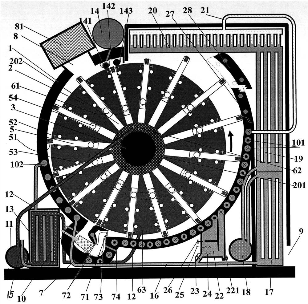
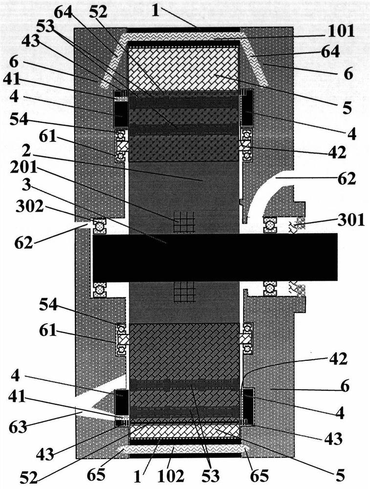
[0040] Among the figure, stator (1), rotor (2), rotor shaft (3), rotor cover (4), sliding vane assembly (5), side cover (6), combustion chamber (7) etc. form the basic work system. The cylindrical rotor (2) with the sliding vane assembly (5) having the vane groove (202) is installed on the rotor shaft (3) with splines, and the middle part of the shaft hole of the spline shaft on the rotor is installed There is a ring groove (201) connecting the sliding vane groove to allow the gas and liquid in the sliding vane groove to circulate freely, so as to avoid compressing the gas when the sliding vane moves up and down in the sliding vane groove, and waste energy; the rotor (2) is fixed by the rotor cover (4). The structure is strengthened to form the rotor assembly; the rotor cover (4) has an oil-gas sealing ring (43) which is used for sealing between the rotor (3) and the side cover (6) and is the same as the piston ring, and the rotor cover (4) on one side There are also lubricati...


PUM


Abstract

The invention discloses a fuel gas-steam combined cycle equal-pressure variable capacitance slide piece rotor engine, and the engine is similar to an ideal variable high-efficiency combustion gas turbine. A stator shaped like an involute curved surface, a cylindrical rotor, a rotor shaft, a rotor cover, a slide piece assembly, a side cover and a combustor form a basic acting system. The stator, the rotor, the side cover and a slide piece enable the interior to be divided into an air gradual compression chamber (like multistage compression) and a gradual expansion chamber (multistage expansion) which is large in size and acts through fuel gas after combustion. During operation, the rotor rotates to inhale air from an air inlet, carries out gradual compression while the slide piece moves, and enables air to enter the combustor from a compressed air outlet and to be mixed with fuel gas. The gas absorbs heat to expand in an equal pressure manner. Because the compression area of an expansion chamber slide piece is larger than the compression area of a compression chamber slide piece by several times and the pressure intensities are equal, the thrust at the expansion chamber side is greater than the resistance of the compression chamber by several times, an external acting force moment is formed, and an equal-pressure expansion work is done. The expanded gas is divided by the slide piece in the expansion room, and the size of the expanded gas becomes large in operation, and then an adiabatic expansion work is done.

Description

technical field [0001] The invention relates to a heat engine, which is a high-efficiency sliding vane rotor engine, and is also a variable high-efficiency gas turbine with closed working gas. Background technique [0002] The structure of the existing piston engine is complex, and the efficiency is not high enough; the efficiency of the best gasoline engine is generally more than 20% during normal operation, and the new Prius released in December 2015 in cooperation with Toyota and Mazda reaches 40%, which is currently commercially available It has the highest efficiency, but its high-efficiency operating range is very low, and its low-speed performance is poor, so it is only suitable for hybrid power generation; diesel engines have better efficiency, but poor comfort and weight; existing rotary engines work in explosive mode, which has low efficiency and pollution Mazda has discontinued production; steam turbines have low crude efficiency; gas turbines have low efficiency ...

Claims


Application Information

Patent Timeline
Patent Type & Authority Patents(China)
IPC IPC(8): F02B55/02F02B53/10F02B55/14F02B55/08F02B53/04F02B53/02F02B45/02F02B45/08F02C6/00
CPCF02B45/02F02B45/08F02B53/02F02B53/04F02B53/10F02B55/02F02B55/08F02B55/14F02C6/00Y02T10/12Y02T10/30
Inventor 钱百成
Owner 钱百成
Why Eureka
Try Eureka