Friction stir welding method for different metal plates

A technology of friction stir and welding method, which is applied in welding equipment, metal processing, metal processing equipment, etc., and can solve the limitation of force on dissimilar metal connectors of single-side lap joint structure, which cannot meet the requirements of welding quality and strength. and other issues, to achieve the effect of improving connection performance, improving forming, and reducing heat input

Active Publication Date: 2016-09-28
725TH RES INST OF CHINA SHIPBUILDING INDAL CORP
View PDF6 Cites 18 Cited by
  • Summary
  • Abstract
  • Description
  • Claims
  • Application Information

AI Technical Summary

Problems solved by technology

[0005] In the prior art, when the friction stir welding method is used to weld two different metal plates, a straight plate type butt joint structure or a single-side lap joint structure is adopted. The former is not only prone to side separation of the two metal plates, but also due to the The generation of compounds reduces the bonding strength, which cannot meet the strength requirements of actual use; the latter reduces the connection strength due to the lack of bonding surfaces, and the latter’s single-side lap structure also limits the force of the obtained dissimilar metal connectors. , in short, the existing welding methods cannot meet the needs of welding quality requirements between dissimilar metal materials, especially dissimilar metal plates

Method used


Image

  • Friction stir welding method for different metal plates
  • Friction stir welding method for different metal plates
  • Friction stir welding method for different metal plates

Examples


Embodiment 1

[0033] A friction stir welding method between dissimilar metal plates, comprising the following steps:

[0034] 1) Determine the relative thickness of the two metal plates to be welded:

[0035] In this example, 5052 aluminum alloy plate and 316L stainless steel plate are used for welding, because the melting point difference between the two is above 600°C, so it can be determined to use two metal plates with different thicknesses. In this example, 5052 aluminum plate with a thickness of 4.5mm is used. The alloy plate is welded with a 4mm thick 316L stainless steel plate (because the melting point of 5052 aluminum alloy is lower than that of 316L stainless steel).

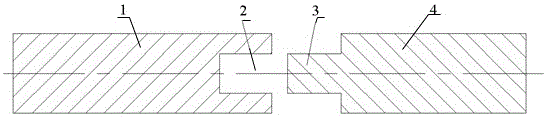
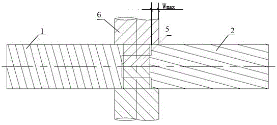
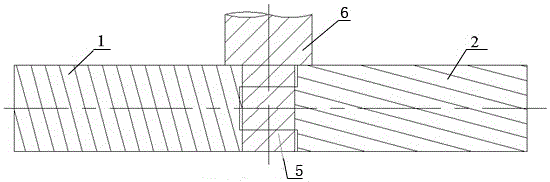
[0036] 2) Process the joint structure at the welding ends of the two metal plates to be welded:

[0037] In this embodiment, a rectangular groove is processed at the welding end of the 5052 aluminum alloy plate with a low melting point. The depth of the rectangular groove is 3 mm, the width of the rectangular groo...

Embodiment 2

[0046] A friction stir welding method between dissimilar metal plates, comprising the following steps:

[0047] 1) Determine the relative thickness of the two metal plates to be welded:

[0048] In this embodiment, TC4 titanium alloy plate and 316L stainless steel plate are selected for welding, because the melting point difference between the two is below 600°C, so it can be determined to use two metal plates with the same thickness. In this embodiment, TC4 titanium alloy with a thickness of 8 mm is used. Plate and 316L stainless steel plate are welded.

[0049] 2) Process the joint structure at the welding ends of the two metal plates to be welded:

[0050] In this embodiment, a rectangular groove is processed at the welding end of the TC4 titanium alloy plate with a low melting point. The depth of the rectangular groove is 5mm, and the width of the rectangular groove is 4mm. The opening direction of the rectangular groove is the same as that of the TC4 titanium alloy plate...

Embodiment 3

[0059] A friction stir welding method between dissimilar metal plates, comprising the following steps:

[0060] 1) Determine the relative thickness of the two metal plates to be welded:

[0061] In this example, 5052 aluminum alloy plate and TA2 pure titanium plate are selected for welding, because the melting point difference between the two is above 600°C (the melting point of 5052 aluminum alloy plate is low, and the melting point of TA2 pure titanium plate is high), so it can be determined to use For two kinds of metal plates with different thicknesses, in this embodiment, a 5052 aluminum alloy plate with a thickness of 10 mm is used for welding with a TA2 pure titanium plate with a thickness of 9 mm.

[0062] 2) Process the joint structure at the welding ends of the two metal plates to be welded:

[0063] In this embodiment, a rectangular groove is processed at the welding end of the 5052 aluminum alloy plate with a low melting point. The depth of the rectangular groove ...


PUM

PropertyMeasurementUnit
thicknessaaaaaaaaaa
widthaaaaaaaaaa
thicknessaaaaaaaaaa

Abstract

The invention provides a friction stir welding method for different metal plates. The friction stir welding method for different metal plates comprises the following steps that (1) the relative thicknesses of two metal plates are determined; (2) connector structures are machined at the welding end of the two metal plates, specifically, a rectangular groove is machined in the welding end of the low-melting point metal plate, and a rectangular boss is machined at the welding end of the high-melting point metal plate, and the height and thickness of the rectangular boss are matched with the depth and width of the rectangular groove correspondingly; (3) whether a transition layer capable of avoiding or reducing generated intermetallic compounds needs to be additionally arranged or nor is determined, specifically, the transition layer is arranged on the surface of the rectangular boss if the ductility of the intermetalic compounds between the two metal plates is not larger than 2%, otherwise, the next step is executed directly; (4) the two metal plates are fixed through clamps; (5) welding technological parameters are set; and (6) welding of the two metal plates is completed through a stirring head according to the set welding technological parameters. According to the friction stir welding method for different metal plates, the welding quality is high, and the stress condition of connectors can be improved.

Description

technical field [0001] The invention relates to the technical field of connection of dissimilar metal plates, in particular to a friction stir welding method between dissimilar metal plates. Background technique [0002] In industrial production, since different metals have different advantages, dissimilar metal connectors obtained by connecting different metals usually have greater practical value. For example, the most widely used non-ferrous metal aluminum and aluminum alloys in today's industry have light weight, high specific strength, corrosion resistance, and good thermal and electrical conductivity; steel, the most commonly used structural material in engineering, has relatively high strength; There is also a titanium and titanium alloy that have been widely used in the field of marine ships, which not only have high specific strength, but also have good corrosion resistance. Therefore, the dissimilar metal connectors obtained by connecting any two of the above three...

Claims


Application Information

Patent Timeline
Patent Type & Authority Applications(China)
IPC IPC(8): B23K20/12B23K20/24B23K20/22B23K33/00B23K103/18B23K101/18
CPCB23K20/122B23K20/22B23K20/24B23K33/00B23K2101/18B23K2103/18
Inventor 高福洋郁炎蒋鹏
Owner 725TH RES INST OF CHINA SHIPBUILDING INDAL CORP
Why Eureka
Try Eureka